
Short answer: CFD thermal management uses simulation to predict how heat moves through solids and cooling fluids, so engineers can find hot spots, size heat sinks and airflow, and compare cooling strategies before building hardware. The key method is conjugate heat transfer, which solves conduction in the solid and convection in the fluid together; transient and coupled thermal-structural analyses extend it to thermal cycling and durability.
Heat is the limiting factor in a growing range of products. Electronics pack more power into smaller volumes, battery packs must stay within a narrow temperature window, and industrial and energy equipment is pushed harder for efficiency. Effective CFD thermal management improves performance and extends service life by showing where heat is generated, how it travels and where the cooling system falls short.
Computational Fluid Dynamics (CFD) models heat transfer, airflow and temperature together. Engineers use it to predict temperature distributions, evaluate heat-sink designs, compare air, liquid and passive cooling, and understand how components respond to changing thermal loads.
What CFD Thermal Management Covers
| Thermal problem | CFD approach | Key outputs |
|---|---|---|
| Electronics and enclosure cooling | Conjugate heat transfer with forced or natural convection | Component and junction temperatures, airflow paths, fan operating point |
| Heat-sink design | Parametric fin studies with conjugate heat transfer | Thermal resistance versus pressure drop, fin efficiency |
| Phase change material (PCM) cooling | Transient melting and solidification models | Melt fraction, time to reach temperature limit, peak temperature |
| Thermal cycling and shock | Transient CFD, coupled with structural analysis | Temperature gradients over time, input to stress and fatigue assessment |
| Liquid cooling and heat exchangers | Internal flow with heat transfer | Heat-transfer rate, flow distribution, pressure drop |
| Rooms, data centers and buildings | Airflow with buoyancy and heat sources | Inlet temperatures, stratification, recirculation |
Electronics Cooling and Heat Sink Optimization with CFD
Electronics cooling simulation is one of the most common thermal applications of CFD consulting. A good model captures heat dissipation from each component, conduction through boards, spreaders and heat sinks, and the airflow that carries heat away. It answers practical questions: will the hottest component stay below its limit, is the fan working at a sensible point on its curve, and is air bypassing the fins instead of passing through them?
Heat-sink design is a trade-off. Closer fin spacing adds surface area but raises flow resistance, so in a fan-driven system more fins can actually reduce airflow through the sink and increase temperature. CFD lets engineers sweep fin count, thickness, height and spacing and find the design with the lowest thermal resistance at the available pressure. Passive options such as phase change materials (PCMs) add another dimension: research such as Thermal Management of Single and Multiple PCMs Based Heat Sinks for Electronics Cooling shows how CFD heat-transfer analysis can compare PCM configurations and predict how long a heat sink can absorb a thermal load before temperatures rise.
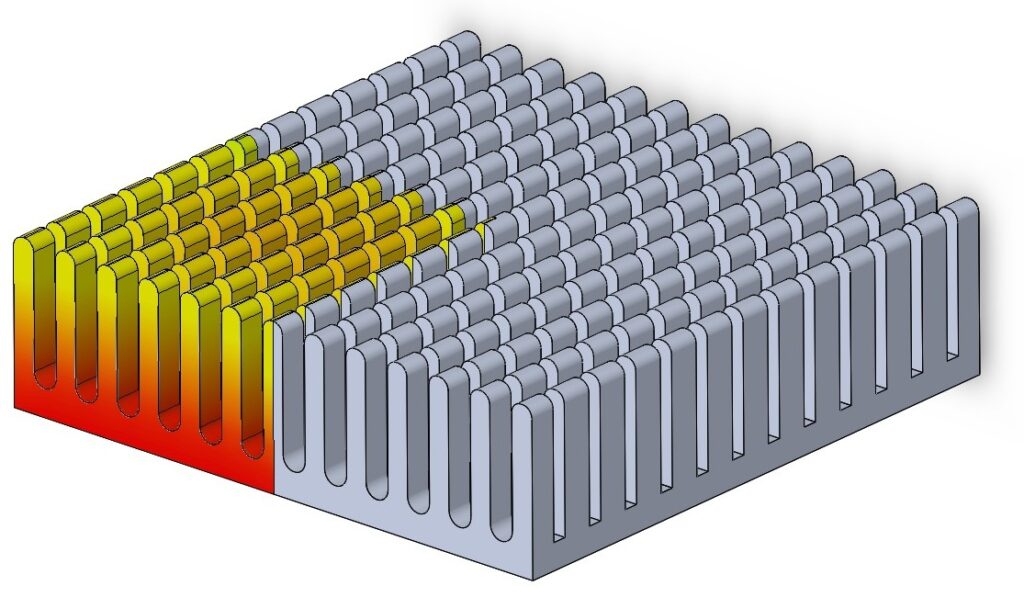
Enhancing Thermal Shock Resistance with Advanced CFD Modeling
Many components fail not from a steady high temperature but from repeated heating and cooling. Cyclic thermal loads create temperature gradients, and the resulting expansion and contraction drive stress and fatigue in joints, solder, interfaces and fins. Transient CFD predicts how temperature fields evolve through each cycle; those fields then feed a structural (finite element) analysis to assess stress and fatigue life.
The study Improvement on the Cyclic Thermal Shock Resistance of Electronics Heat Sinks Using Two-Objective Optimization illustrates how heat-transfer analysis combined with optimization can improve heat-sink durability under cyclic loading. CFD consultants can set up these transient and coupled analyses so designs are robust against thermal cycling, not just adequate at steady state.

Linking CFD Thermal Management to Broader Engineering Applications
The same physics appears well beyond electronics: battery packs, power electronics, heat exchangers, industrial ovens and dryers, energy systems, aerospace components and large HVAC systems. In each case the questions are similar: where does heat go, where does it accumulate, and which design change moves it most efficiently? Our engineering simulation consulting covers these applications, including industrial systems and renewable energy equipment, and manufacturers in Sydney, Melbourne and other cities can work directly with our computational fluid dynamics consultants in Australia. For room- and facility-scale thermal problems, see our article on CFD for data center cooling.

Emerging Trends: AI-Enhanced CFD and Passive Cooling Innovations
AI-driven simulation is starting to speed up thermal design. Surrogate models trained on CFD results can estimate temperatures for new design variants in a fraction of the time of a full simulation, which makes wider design-space exploration practical. They are only as reliable as their training data, so final designs should still be checked with full CFD.
Passive cooling is another active area. Metal foams, PCM-embedded heat sinks and, in research settings, nanofluids aim to reduce reliance on fans and pumps, improving energy efficiency and reliability. CFD is how these concepts are evaluated before prototypes are made, because their performance depends strongly on geometry, material properties and operating conditions.
Getting Reliable Thermal Results
Thermal predictions are most sensitive to heat-load data, contact resistances between parts, material properties, fan curves and near-wall mesh resolution. An energy balance (heat in versus heat out) is a simple but powerful check. Our guide to CFD validation explains how to confirm results are trustworthy. For quick first estimates before a full simulation, try our Heat Transfer Calculator, Nusselt Number Calculator or Heat Exchanger Calculator.
Frequently Asked Questions
What is conjugate heat transfer in CFD?
It is the simultaneous solution of heat conduction in solid parts and convective heat transfer in the surrounding fluid, with temperature and heat flux matched at their interfaces. It is the standard approach for electronics cooling and heat-sink design.
Can CFD predict thermal fatigue?
CFD predicts the transient temperature fields. Stress and fatigue life come from a structural analysis that uses those temperatures as input, so thermal fatigue assessment is a coupled CFD and FEA task.
More fins or fewer fins: what gives a better heat sink?
It depends on the available airflow and pressure. More fins add area but increase resistance; beyond an optimum, airflow falls and temperatures rise. CFD finds that optimum for your fan and enclosure.
Facing a heat-control problem? Explore our CFD simulation services for thermal and fluid-flow analysis, including heat-sink design and thermal-cycling studies, or see how our product design services bring simulation into your development process. Whether you need expert CFD consultancy for a specific challenge or structured CFD Research Support and CFD Mentorship to build internal capability, browse our CFD simulation projects or contact CFD Vision to discuss your project.
About the author: Ryan Mozafari leads CFD Vision. He holds a PhD in thermal-fluid science from Macquarie University and has more than 10 years of experience applying CFD to industrial and academic problems. LinkedIn · Google Scholar