
Skip to content

AS/NZS 3500.1 Water Pipe Sizing Calculator: Loading Units, Velocity and Pressure

Sizing a cold or hot water service is one of the most repeated calculations in hydraulic design. In Australia and New Zealand, the method comes from AS/NZS 3500.1, which the Plumbing Code of Australia calls up for water services. In practice, the steps are always the same: total the loading units, convert them to a probable simultaneous flow, pick a pipe that keeps velocity within the limit, and confirm there is enough pressure left at the most disadvantaged outlet.

This free AS3500 pipe sizing calculator supports that workflow in one place. It totals your fixture schedule, takes the probable simultaneous flow you read from the Standard, compares every standard copper and PE size side by side, and then tracks pressure section by section along the index run. Finally, it exports a printable summary or a CSV file that you can attach to your design records.

Pressure losses use the Darcy–Weisbach equation with temperature-corrected water properties, rather than a fixed chart, so the same tool works for cold water and for heated water services. For the underlying friction calculation on its own, the pipe flow pressure drop calculator gives more detail on fittings and minor losses.

Quick answer

To size a water pipe to AS/NZS 3500.1, add up the loading units of every fixture the pipe serves, read the probable simultaneous flow for that total from the Standard, and choose the smallest pipe that keeps velocity at or below 3.0 m/s. Then check that the pressure remaining at the furthest or highest outlet stays above the required minimum after friction and elevation losses.
Jump to the pipe sizing calculator ↓


AS-NZS 3500.1 Water Pipe Sizing Calculator- Loading Units, Velocity and Pressure

AS/NZS 3500.1 Water Pipe Sizing Calculator

Total the loading units for a fixture schedule, size a cold or hot water pipe against a velocity limit, then check the residual pressure along the index run. The calculator performs the hydraulics only: loading units, the probable simultaneous flow and pressure limits are entered by you from AS/NZS 3500.1 or your design basis, so every result stays traceable. Preloaded values are illustrative examples.

1. Fixture Schedule and Loading Units

List the fixtures served by the pipe section. Enter the loading units per fixture from AS/NZS 3500.1; the values shown are illustrative placeholders, not quoted from the Standard.

Total loading units: —

2. Design Flow and Pipe Data

Pipe Sizing Results

Smallest size within your limits—
Velocity—
Pressure gradient—
Design flow—
SizeID (mm)Velocity (m/s)ReynoldsFriction factorkPa/mm head / 100 mStatus
Method: Darcy–Weisbach with the Colebrook–White friction factor, water density and viscosity evaluated at the entered temperature. Pipe internal diameters are calculated from nominal outside diameter and wall thickness; confirm against the manufacturer’s data for the product you specify. Fittings and valves are not included in the straight-pipe gradient.

Supply and Limits

Index Run Sections

Enter each section from the supply to the most disadvantaged outlet. Fittings allowance adds a percentage to the straight length; rise is the elevation gain over the section (negative for a fall).

Index Run Results

Residual pressure at outlet—
Total friction loss—
Static (elevation) change—
Highest section velocity—
SectionFlow (L/s)SizeVelocity (m/s)kPa/mEquiv. length (m)Friction (kPa)Static (kPa)Pressure at end (kPa)
Pressure along the index run
Water hammer, pump or valve performance, cavitation or flow balancing in a complex network? A hand calculation cannot resolve those. Ask about a hydraulic CFD study.
Method: pressure at the end of each section = pressure at start − friction loss − ρ·g·rise. Friction loss = pressure gradient × straight length × (1 + fittings allowance). Pressure-limiting valves, meters, backflow devices and water heaters must be added as separate sections or losses. The minimum outlet pressure is an editable default and the maximum is optional; confirm both for your project against AS/NZS 3500.1, the fixture manufacturers and the water agency’s requirements.
'); w.document.close();w.focus();setTimeout(function(){w.print();},300); } function printSize(){ if(!sizeData){return;}var d=sizeData; var h='

Water Pipe Sizing

'+esc(d.mat)+' · '+esc(dateStr())+'
'; h+='
Design flow '+fmt(d.Q,3)+' L/s at '+fmt(d.T,0)+' °C. Smallest size meeting the '+fmt(d.vmax,2)+' m/s velocity limit'+(d.gmax!==null?' and '+fmt(d.gmax,3)+' kPa/m gradient limit':'')+': '+(d.pick?esc(d.pick.label):'none in range')+'.
'; h+='

Fixture schedule

'; d.fx.forEach(function(f){h+='';}); h+='
FixtureQtyLU eachLU total
'+esc(f.n)+''+fmt(f.q,0)+''+fmt(f.lu,2)+''+(f.ok?fmt(f.q*f.lu,2):'—')+'
Total'+fmt(d.lu,1)+'
'; h+='

Size comparison

'; d.rows.forEach(function(x){h+='';}); h+='
SizeID mmVelocity m/skPa/mStatus
'+esc(x.label)+''+fmt(x.idmm,2)+''+fmt(x.h.v,2)+''+fmt(x.h.gradKPa,3)+''+(x===d.pick?'Selected':(x.ok?'OK':(!x.okV?'Velocity too high':'Gradient too high')))+'
'; if(d.warn.length){h+='
'+esc(d.warn.join(' '))+'
';} h+='

Basis

Loading units and the probable simultaneous flow were entered by the designer from AS/NZS 3500.1. Friction by Darcy–Weisbach with the Colebrook–White friction factor; water properties at the stated temperature.

'; printDoc('Water pipe sizing',h); } function printRun(){ if(!runData){return;}var d=runData; var h='

Index Run Pressure Check

'+esc(d.name)+' · '+esc(d.mat)+' · '+esc(dateStr())+'
'; h+='
Residual pressure at the outlet: '+fmt(d.P,1)+' kPa ('+(d.pass?'meets':'below')+' the '+fmt(d.Pmin,0)+' kPa minimum), from '+fmt(d.Pin,0)+' kPa available. Friction loss '+fmt(d.fricTot,1)+' kPa; static change '+fmt(d.statTot,1)+' kPa.
'; h+='

Sections

'; d.secs.forEach(function(s){h+='';}); h+='
SectionFlow L/sSizeVelocitykPa/mEquiv. mFriction kPaStatic kPaP end kPa
'+esc(s.n)+''+fmt(s.q,3)+''+esc(s.size)+''+fmt(s.v,2)+''+fmt(s.g,3)+''+fmt(s.Le,1)+''+fmt(s.fr,1)+''+fmt(s.st,1)+''+fmt(s.Pend,1)+'
'; h+='

Pressure along the index run

'+chartSVG(d)+'
'; if(d.warn.length){h+='
'+esc(d.warn.join(' '))+'
';} h+='

Basis

Pressure at the end of each section = start pressure − gradient × length × (1 + fittings allowance) − ρ·g·rise, at '+fmt(d.T,0)+' °C. Meters, valves, backflow devices and heaters are not included unless entered as sections.

'; printDoc('Index run pressure check',h); }$('pzAddFx').addEventListener('click',function(){addFx();}); $('pzCalcSize').addEventListener('click',calcSize); $('pzResetSize').addEventListener('click',resetSize); $('pzPrintSize').addEventListener('click',printSize); $('pzCsvSize').addEventListener('click',csvSize); $('pzAddSec').addEventListener('click',function(){addSec();}); $('pzCalcRun').addEventListener('click',calcRun); $('pzResetRun').addEventListener('click',resetRun); $('pzPrintRun').addEventListener('click',printRun); $('pzCsvRun').addEventListener('click',csvRun); $('pzPngRun').addEventListener('click',chartPng); resetSize();resetRun(); })();

What the Pipe Sizing Calculator Does

The calculator is split into two connected tools that mirror how hydraulic engineers and plumbers actually work.

  • Size a pipe: totals the loading units of a fixture schedule, then compares every standard size for the chosen material, showing velocity, Reynolds number, friction factor and pressure gradient, and highlights the smallest size that meets your limits.
  • Index run pressure check: follows the critical path from the meter to the most disadvantaged outlet, section by section, and reports friction loss, elevation loss and the residual pressure at the end of each section.
  • Materials: copper Type B tube to AS 1432, PE100 SDR11 (PN16) pipe, or any custom internal diameter and roughness.
  • Documentation: a printable summary, which you can save as a PDF, and a CSV export with every input, result and check.

Importantly, the tool performs the hydraulics but does not implement the Standard’s tables or decide which values apply. It does not reproduce the loading unit or flow tables of AS/NZS 3500.1, which are copyright material, and it does not convert loading units to flow for you. Instead, you enter those values from your copy of the Standard, and the summary shows exactly which numbers you used. The values preloaded in the fields are illustrative placeholders, not quoted from the Standard.


Loading Units and Probable Simultaneous Flow

Sizing a pipe for every fixture running at full flow at the same time would produce grossly oversized pipework. In reality, a basin, a shower and a dishwasher in the same building rarely draw water at the same instant, and the larger the building, the smaller the fraction of fixtures operating together.

Loading units capture this diversity. Each fixture type carries a loading unit value that reflects its flow rate, how long it runs and how often it is used. Adding them up gives a single number for the pipe section, and the Standard then converts that total into a probable simultaneous flow in L/s. Because the conversion is non-linear, doubling the loading units does not double the design flow, which is why large buildings end up with surprisingly modest mains.

Two practical points are worth remembering. First, fixtures with long, continuous draws, such as irrigation or process equipment, may need to be treated as a continuous flow rather than through loading units, so check how your governing standard handles them. Second, each pipe section carries only the loading units downstream of it, so the design flow falls as you move along the run towards the furthest outlet.


Velocity Limit and Pipe Selection

Once the design flow is known, velocity follows directly from the internal diameter:

v=4QπD2v = \frac{4Q}{\pi D^{2}}

AS/NZS 3500.1 limits water velocity in pipework to 3.0 m/s. Higher velocities increase noise, erosion of copper, especially at fittings, and the pressure surge when a valve closes quickly. Many designers therefore choose a lower design velocity for quieter operation, particularly for hot water and for branches near bedrooms, and the calculator lets you set your own target.

Note that nominal size and internal diameter are not the same thing. A DN20 copper tube has an internal diameter of about 17 mm, whereas a 20 mm OD PE pipe has a bore of only about 16 mm. For this reason, the calculator works from the actual internal diameter of each product, calculated from its outside diameter and wall thickness, rather than from the nominal size.


Pressure Loss with Darcy–Weisbach

Friction loss per metre of straight pipe is calculated with the Darcy–Weisbach equation:

ΔpL=f1Dρv22\frac{\Delta p}{L} = f \frac{1}{D} \frac{\rho v^{2}}{2}

The Darcy friction factor f comes from the Colebrook–White equation, which accounts for both the Reynolds number and the relative roughness of the pipe wall:

1f=−2log10(ε/D3.7+2.51Ref)\frac{1}{\sqrt{f}} = -2\log_{10}\left(\frac{\varepsilon/D}{3.7} + \frac{2.51}{Re\sqrt{f}}\right)

Water density and viscosity are evaluated at the temperature you enter. This matters more than many people expect: water at 60 °C has less than half the viscosity of water at 20 °C, so it has a higher Reynolds number and a slightly lower friction loss for the same flow. If you want to explore the flow regime in more depth, the Reynolds number calculator covers it in detail.

Darcy–Weisbach is used here instead of the Hazen–Williams formula because it holds for any temperature and remains physically consistent across pipe sizes and materials. Hazen–Williams is an empirical fit for cold water in turbulent flow, and its coefficient has to be chosen by judgement.


Index Run and Residual Pressure

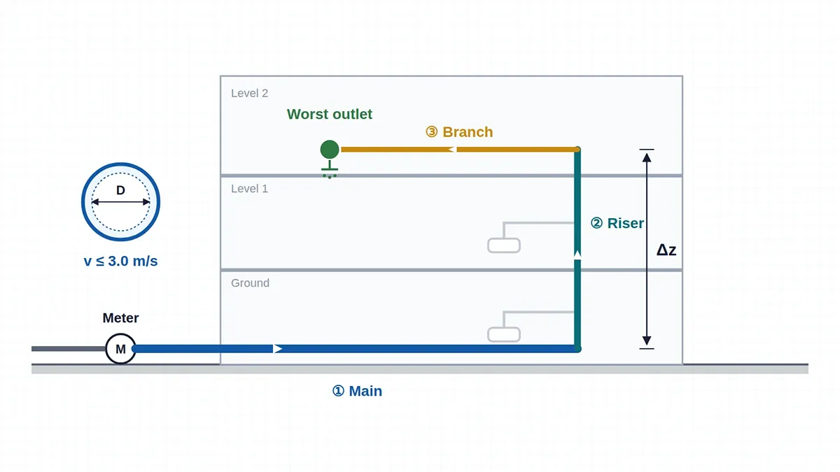
The index run is the path from the supply to the outlet with the least pressure available, usually the furthest or the highest fixture. If that outlet works, every other outlet on the system has more pressure in hand. For each section, the calculator applies:

Pend=Pstart−ΔpLL(1+k)−ρgΔzP_{\mathrm{end}} = P_{\mathrm{start}} – \frac{\Delta p}{L} L (1 + k) – \rho g \Delta z

Here, k is the fittings allowance as a fraction of the straight length, and Δz is the rise over the section. Every metre of rise costs about 9.8 kPa, so in multi-storey buildings elevation often dominates friction. In the worked example, a 6.5 m rise up the riser costs more pressure than all the pipe friction in the run combined.

AS/NZS 3500.1 sets a minimum pressure at outlets, and the calculator uses 50 kPa as an editable default. However, many fixtures and appliances, such as thermostatic mixing valves, instantaneous water heaters and some tapware, need considerably more to perform well, so check the manufacturer’s minimum operating pressure for the critical fixture. At the other end, maximum pressure limits also apply at outlets, and pressure-limiting valves are commonly fitted where mains pressure is high; enter the limit that applies to your project if you want the calculator to flag it. Add meters, backflow prevention devices, pressure-limiting valves and water heaters as their own losses, since they often take a significant share of the available pressure.


When a Hydraulic System Needs More Than Pipe Sizing

Standard pipe sizing assumes steady flow, uniform velocity across each section and well-understood losses through fittings. Those assumptions hold for typical water services, yet they break down in several situations that hydraulic engineers meet regularly:

  • Water hammer and pressure surge after fast valve closure or pump trip, where the pressure rise scales with the change in velocity and the wave speed in the pipe.
  • Control valves, pressure-reducing valves and balancing valves, where cavitation, noise and actual flow coefficients depend on the internal geometry, as in this CFD simulation of a control valve.
  • Pumps and booster sets, where suction conditions, inlet swirl and impeller performance decide whether the system reaches its duty point, as explored in this centrifugal pump impeller CFD study.
  • Manifolds, headers and tanks, where flow distribution between branches is uneven and mixing or stagnation affects water quality and temperature.

In these cases, computational fluid dynamics shows what happens inside the component rather than averaging it into a single loss coefficient. CFD Vision provides CFD analysis services for hydraulic consultants, plumbing engineers and equipment manufacturers, delivered remotely for clients in Australia and overseas.


Limitations and Responsible Use

This calculator is a hydraulic and documentation aid for preliminary design. It does not implement the tables or procedures of AS/NZS 3500.1, Standards Australia and Standards New Zealand did not develop it and do not endorse it, and its results do not determine compliance with AS/NZS 3500.1, the Plumbing Code of Australia or any water agency’s requirements. Pipe dimensions are calculated from nominal outside diameters and wall thicknesses, so confirm them against the data for the product you specify. You remain responsible for the loading units, flows, pressure limits and fittings allowances you enter, and for having the design checked by a suitably qualified person. All calculations run in your browser, so the calculator does not store or send any project data.


Frequently Asked Questions

What is the maximum water velocity under AS/NZS 3500.1?

The Standard limits velocity in water service pipework to 3.0 m/s. Many designers choose a lower target for quieter operation and to reduce erosion and water hammer, particularly in hot water and residential branches.

Why do I have to enter the loading units myself?

The loading unit and flow tables are copyright material of Standards Australia and Standards New Zealand. Entering them yourself also keeps the calculation traceable to the edition and table you used.

Can I use the calculator for hot water?

Yes. Set the water temperature, and the calculator adjusts density and viscosity accordingly. For heated water, also check flow and return circuits, temperature ratings of plastic pipes and any lower velocity targets that apply to your project.

What fittings allowance should I use?

A percentage allowance on straight length is a common shortcut for early design, with higher percentages for short runs with many fittings. For final design, or where valves and specialist components dominate, calculate each fitting’s loss with its own K value or equivalent length.

Does it size sanitary drainage or fire services?

No. Drainage is covered by other parts of AS/NZS 3500 and uses fixture units and grades rather than pressure, while fire services follow their own standards and flow requirements.


Facing a hydraulic problem a pipe chart cannot answer?

Send your drawings and operating data to [email protected] for a scoped CFD proposal covering valves, pumps, manifolds, water hammer or flow distribution. CFD Vision can sign an NDA before you share any files.

More free tools: engineering calculators for heat transfer, fluid flow and CFD, including the pipe flow pressure drop calculator and the Reynolds number calculator.