
Use this free CFD Y+ Calculator to estimate the first-cell height required near a wall for computational fluid dynamics simulations. The calculator determines an approximate wall-normal distance for a specified target Y+ using flow velocity, characteristic length, fluid density, dynamic viscosity, Reynolds number, estimated skin-friction coefficient, wall shear stress, and friction velocity.
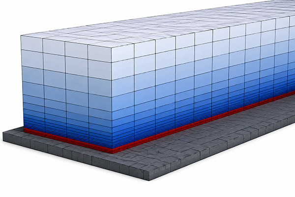
Near-wall mesh resolution is particularly important in CFD simulations involving turbulent boundary layers, aerodynamic drag, wall shear stress, flow separation, pressure losses, and convective heat transfer. Selecting a suitable first-cell height before generating inflation or prism layers can help create a CFD mesh that is consistent with the selected turbulence model and near-wall treatment.
If you are still determining the flow regime before creating your mesh, you can also use the Reynolds Number Calculator to evaluate the relationship between inertial and viscous effects.
Quick answer
y = y⁺ · ν / uτ, with uτ = √(τw/ρ) and ν = μ/ρ. Before solving, the calculator estimates wall shear stress from the flat-plate correlation Cf = 0.026 / Re1/7.
Typical targets: y⁺ ≈ 1 for wall-resolved models such as SST k-ω, and y⁺ above about 30 for wall functions. Use the result to set the first layer of your inflation (prism) mesh, then check the actual y⁺ after the solution converges.
CFD Y+ calculator
CFD Mesh First-Cell Height / Y+ Calculator
Estimate the near-wall first-cell-center distance required for a target Y+ value in a CFD simulation. The calculation uses flow velocity, characteristic length, fluid density, dynamic viscosity and an estimated turbulent skin-friction coefficient (a Prandtl 1/7-power-law flat-plate correlation, Cf = 0.026/Re^(1/7); see Schlichting, Boundary-Layer Theory).
Re = ρUL / μCf = 0.026 / Re^(1/7)τw = 0.5 × ρ × U² × Cfuτ = √(τw / ρ)ν = μ / ρy = Y+ × ν / uτCFD Y+ and First-Cell Height Calculator
Enter the principal flow conditions and select a target Y+ value. The calculator provides an engineering estimate of the wall-normal distance from the wall to the center of the first computational cell.
Calculator Inputs
- Reference velocity, U [m/s]
- Characteristic length, L [m]
- Fluid density, ρ [kg/m³]
- Dynamic viscosity, μ [Pa·s]
- Target Y+ [-]
Typical fluid presets such as air and water may also be provided for convenience.
Calculator Outputs
The calculator determines:
- Reynolds number, Re
- Kinematic viscosity, ν
- Estimated skin-friction coefficient, Cf
- Estimated wall shear stress, τw
- Friction velocity, uτ
- First-cell-center distance, y [m]
- First-cell-center distance [mm]
The calculated distance is intended primarily as an initial value for boundary-layer mesh generation.
The calculated first-cell height is an engineering estimate. Actual Y+ values depend on the local wall shear stress obtained from the CFD solution and should therefore be evaluated after the simulation has converged.
What Is Y+ in CFD Simulation?
Y+, usually pronounced "y-plus," is a nondimensional wall distance used to describe the location of a computational cell relative to a solid wall in wall-bounded flows. It is an important near-wall parameter in many CFD simulations, particularly when turbulence models are used to predict boundary layers, wall shear stress, flow separation, aerodynamic drag, and convective heat transfer.
Y+ is defined as:
y+ = y uτ / ν
where:
- y+ = dimensionless wall distance
- y = wall-normal distance to the first computational point
- uτ = friction velocity
- ν = kinematic viscosity
The friction velocity is:
uτ = √(τw / ρ)
where:
- τw = wall shear stress
- ρ = fluid density
The kinematic viscosity is:
ν = μ / ρ
where μ is the dynamic viscosity.
Therefore, the required wall-normal distance for a specified target Y+ can be estimated from:
y = y+ ν / uτ
or equivalently:
y = y+ μ / (ρuτ)
These definitions follow the standard wall-coordinate formulation documented by NASA Glenn Research Center, which relates Y+ to wall distance, friction velocity, and kinematic viscosity.
Selecting an appropriate Y+ is therefore an important part of professional CFD analysis, but the target value must be considered together with the turbulence model, near-wall treatment, mesh resolution, and physics of the engineering problem.
Why Is First-Cell Height Important in CFD Simulation and Meshing?
The flow immediately adjacent to a no-slip wall contains very large velocity gradients. In thermal CFD simulations, similarly strong temperature gradients can develop close to heated or cooled surfaces.
For this reason, CFD mesh design must provide appropriate near-wall resolution for the selected turbulence model and wall treatment.
First-cell height can influence predictions of:
- wall shear stress
- aerodynamic drag
- boundary-layer development
- flow separation and reattachment
- pressure loss
- convective heat transfer
- surface heat flux
- turbulence production
However, selecting an appropriate first-cell height is only one part of a reliable CFD meshing strategy.
In professional CFD simulation services, the first-cell height should not be considered independently. Inflation-layer thickness, layer growth rate, mesh quality, turbulence modeling, convergence behavior, and mesh-independence assessment are also important parts of a reliable CFD methodology.
The turbulence model itself also influences how the near-wall region should be treated. For a deeper discussion, see Introduction: Why Turbulent Models Matter in CFD.
What Y+ Value Should You Target in CFD Simulations?
There is no universal Y+ value suitable for every CFD simulation.
The appropriate target depends on the turbulence model, near-wall treatment, Reynolds number, geometry, computational resources, flow physics, and the quantities that need to be predicted accurately.
Y+ ≈ 1
For simulations intended to resolve the viscous sublayer directly, a first-cell Y+ close to 1 is commonly targeted.
This approach is often appropriate when accurate predictions of wall shear stress, boundary-layer behavior, separation, aerodynamic drag, or surface heat transfer are important.
Y+ Greater Than Approximately 30
Wall-function approaches typically place the first computational point within the logarithmic region of the turbulent boundary layer rather than resolving the viscous sublayer directly.
For these approaches, Y+ values greater than approximately 30 are commonly associated with the logarithmic region, although the appropriate range depends on the particular wall treatment and solver implementation.
The Ansys Fluent Theory Guide discusses near-wall treatment for ω-based turbulence models and the relationship between near-wall grid resolution and Y+.
Values located in the intermediate buffer region require particular care because they may not correspond cleanly to either idealized treatment.
Y+ and Turbulence Models in CFD Simulations
The appropriate Y+ range in CFD simulations depends strongly on the turbulence model and near-wall treatment.
For wall-resolved approaches, the computational mesh must provide sufficient near-wall resolution to represent the viscosity-dominated region. Wall-function approaches use a different strategy and generally position the first computational point farther from the wall.
This relationship between Y+, turbulence modeling, and mesh resolution is one reason why professional CFD consulting should not rely on a universal first-cell-height value for every engineering problem.
SST k-ω Turbulence Model
The SST k-ω turbulence model is widely used for external aerodynamics, adverse pressure gradients, separated flows, turbomachinery, and other engineering applications.
For wall-resolved applications, a target Y+ close to 1 is commonly used so that the first computational cell is positioned within the viscosity-dominated near-wall region.
SST k-ω is particularly useful in many aerodynamic problems where separation and near-wall behavior are important. A practical discussion of aerodynamic CFD applications can be found in Optimizing Aerodynamic Performance with CFD Simulation.
k-ε Turbulence Models
The appropriate Y+ strategy for k-ε simulations depends on the selected near-wall treatment.
Traditional wall-function approaches generally rely on positioning the near-wall cell within an appropriate portion of the logarithmic boundary layer rather than directly resolving the viscous sublayer.
Other near-wall treatments can permit substantially finer meshes.
This is why specifying "Y+ = 1" or "Y+ = 30" without considering the turbulence model, wall treatment, and simulation objective is not sufficient for professional computational fluid dynamics analysis.
How Does the CFD Y+ Calculator Estimate First-Cell Height?
The main challenge when estimating first-cell height before performing a CFD simulation is that the actual wall shear stress is not yet known.
The calculator therefore estimates wall shear stress from the specified flow conditions using an approximate skin-friction correlation.
Step 1: Calculate Reynolds Number
The Reynolds number is calculated as:
Re = ρUL / μ
where:
- ρ = fluid density
- U = reference velocity
- L = characteristic length
- μ = dynamic viscosity
Reynolds number describes the relative importance of inertial and viscous effects within a flow.
You can calculate and explore this parameter separately using CFD Vision's Reynolds Number Calculator.
Step 2: Estimate the Skin-Friction Coefficient
For an approximate turbulent boundary-layer calculation, the calculator uses:
Cf = 0.026 / Re^(1/7)
This should be understood as an approximate turbulent flat-plate skin-friction correlation rather than a universal expression for every CFD problem.
Complex geometry, transition, pressure gradients, surface roughness, flow separation, compressibility, and three-dimensional effects can produce substantially different local wall shear stresses.
Step 3: Calculate Wall Shear Stress
The estimated wall shear stress is calculated as:
τw = 0.5 ρ U² Cf
Step 4: Calculate Friction Velocity
The friction velocity becomes:
uτ = √(τw / ρ)
The relationship between friction velocity and Y+ is documented in the NASA CFPOST User's Guide.
Step 5: Calculate First-Cell Distance
Finally:
y = y+ ν / uτ
where:
ν = μ / ρ
The resulting value provides an initial estimate of the distance between the wall and the center of the first computational cell.
Why Is CFD First-Cell Height Only an Initial Estimate?
A First Cell Height Calculator cannot know the final wall shear stress before the CFD equations have actually been solved.
The calculated result therefore represents an initial meshing estimate rather than a guaranteed final Y+ value.
For example, a complex aerodynamic geometry may contain:
- stagnation regions
- accelerated flow
- adverse pressure gradients
- separated flow
- reattachment regions
- wakes
- curved surfaces
Each of these conditions can change the local wall shear stress.
This can be observed in external-flow problems such as Fluid Flow Over a Cylinder: CFD Reynolds Number Visualization, where flow conditions vary considerably around the cylinder despite a constant upstream velocity.
Consequently, the actual surface Y+ distribution should be examined after the CFD simulation has been solved.
First-Cell Height and Boundary-Layer Meshing in CFD Analysis
Achieving the desired Y+ does not automatically mean that a CFD mesh is adequate.
A reliable boundary-layer mesh for computational fluid dynamics analysis should also consider:
- number of prism or inflation layers
- total inflation thickness
- layer growth rate
- expected boundary-layer thickness
- streamwise resolution
- spanwise resolution
- local curvature
- separation regions
- geometric transitions
- cell skewness and orthogonal quality
For example, a simulation may achieve Y+ ≈ 1 at the first cell while containing too few computational cells across the remainder of the boundary layer. Such a mesh can still produce inadequate predictions despite apparently satisfying the desired Y+ criterion.
For professional CFD analysis services, Y+ should therefore be treated as one component of mesh verification rather than as an independent measure of simulation accuracy.
CFD Simulation Workflow for Y+ Verification
A practical workflow for engineering CFD simulations is:
Estimate target Y+ → Calculate first-cell height → Generate inflation layers → Run the CFD simulation → Examine the surface Y+ distribution → Refine the mesh if required → Repeat
This iterative procedure is considerably more reliable than assuming that the initial calculated value will produce exactly the desired Y+ everywhere on the geometry.
The process should ideally be combined with mesh-independence assessment and appropriate verification of important engineering quantities such as pressure drop, drag, lift, heat-transfer rate, wall temperature, or flow distribution.
Engineers and researchers who want to develop a deeper understanding of mesh generation, turbulence modeling, solver settings, and CFD methodology can also explore CFD Vision's CFD Training and ANSYS Fluent Support.
CFD Simulation Example: First-Cell Height for External Airflow
Consider airflow over an engineering component with:
Velocity: U = 30 m/s
Characteristic length: L = 1 m
Air density: ρ = 1.225 kg/m³
Dynamic viscosity: μ = 1.789 × 10⁻⁵ Pa·s
Target wall distance: Y+ = 1
The CFD Y+ Calculator first determines the Reynolds number. It then estimates the skin-friction coefficient and uses this value to calculate the wall shear stress and friction velocity.
Finally, the required first-cell-center distance is obtained from:
y = y+ν/uτ
Result: with these inputs, Re ≈ 2.05 × 10⁶, Cf ≈ 0.00326, τw ≈ 1.80 Pa and uτ ≈ 1.21 m/s, giving a first-cell-center distance of y ≈ 1.2 × 10⁻⁵ m (about 0.012 mm). For a cell-centred finite-volume solver, the corresponding first-layer thickness is roughly twice this value.
This value can be used as an initial reference when generating prism or inflation layers for the CFD mesh.
After solving the simulation, however, the actual Y+ contours should be evaluated across the geometry. Regions involving acceleration, separation, reattachment, or other complex flow behavior may differ significantly from the preliminary estimate.
Engineering Applications of the CFD Y+ Calculator
The calculator can assist with preliminary mesh preparation for many engineering CFD simulations, including:
- automotive aerodynamics
- aircraft and airfoil simulations
- HVAC airflow
- heat exchangers
- electronics cooling
- internal pipe and duct flows
- turbomachinery
- pumps
- industrial equipment
- building aerodynamics
- thermal management
- external flow around engineering products
- simulation-driven product development
For aerodynamic applications in particular, near-wall resolution can directly influence drag, separation, and boundary-layer predictions. CFD Vision's article on The Stall Process in Aerodynamics: CFD Aerodynamics Simulation provides further context on the importance of boundary-layer behavior and flow separation.
For thermal CFD problems, near-wall resolution can also influence predicted convective heat-transfer coefficients and surface heat flux. The fundamentals of convective heat transfer can be explored further with the Nusselt Number Calculator for Convective Heat Transfer.
Y+ in CFD-Based Product Design and Engineering Optimization
Near-wall mesh resolution becomes particularly important when CFD simulation is used not simply to visualize a flow field but to compare engineering designs quantitatively.
Applications can include:
- reducing aerodynamic drag
- improving cooling performance
- minimizing pressure losses
- optimizing duct geometry
- improving heat-transfer surfaces
- reducing flow separation
- evaluating alternative product geometries
When multiple designs are compared, inconsistent boundary-layer resolution can introduce numerical differences that may be incorrectly interpreted as genuine physical improvements.
A consistent CFD meshing methodology is therefore particularly important when simulation is integrated into engineering design and optimization.
For more information about this workflow, see CFD in Product Development: From Engineering Concept to Simulation-Driven Design and CFD Vision's dedicated Product Development service.
Limitations of Y+ and First-Cell Height Calculations for CFD
This calculator should not be treated as a replacement for CFD mesh verification.
Its result is based on simplified assumptions and an approximate skin-friction correlation. The calculation may become less representative for flows involving:
- strong pressure gradients
- laminar-to-turbulent transition
- separated flow
- rotating systems
- significant surface roughness
- highly curved surfaces
- compressible or high-Mach-number flow
- multiphase flow
- strong buoyancy effects
- complex three-dimensional boundary layers
In these situations, the calculated first-cell height is best treated as an initial mesh-design estimate.
The final mesh should be evaluated using the actual CFD simulation results, Y+ contours, mesh-independence studies, convergence behavior, and the requirements of the selected turbulence model and wall treatment.
From Y+ Estimation to Professional CFD Simulation Services
A CFD Y+ Calculator or First Cell Height Calculator provides a useful starting point for near-wall mesh design, but reliable CFD simulation requires much more than calculating the first inflation layer.
Geometry preparation, mesh quality, boundary-layer resolution, turbulence modeling, boundary conditions, numerical schemes, convergence monitoring, mesh independence, validation, and engineering interpretation all influence the reliability of a computational fluid dynamics analysis.
For industrial applications where simplified engineering calculations cannot adequately represent the flow physics, CFD Vision provides professional CFD simulation services and CFD consulting for fluid flow, heat transfer, aerodynamics, thermal management, HVAC systems, industrial equipment, and product-development applications.
Professional computational fluid dynamics consulting can help determine an appropriate meshing strategy, turbulence model, boundary conditions, solver configuration, verification procedure, and simulation methodology for complex engineering problems.
You can also learn more about CFD Vision and its approach to engineering simulation on the About CFD Vision page.
CFD Y+ Calculator FAQ
What first-cell height do I need for y+ = 1?
It depends on velocity, fluid properties and length scale. For air at 30 m/s over a 1 m body, the estimate is about 1.2 × 10⁻⁵ m (0.012 mm) to the first cell centre. Enter your own conditions in the calculator above, then confirm the actual y+ contours after solving.
How many inflation layers should I use?
Enough layers to resolve the boundary layer smoothly, commonly around 10–20 layers with a growth rate of about 1.1–1.2, so that the total inflation thickness covers the expected boundary-layer thickness. Always confirm with post-solution y+ contours and a mesh-independence check.
Is the result the first-layer height or the distance to the cell centre?
This calculator returns the wall distance to the centre of the first cell. Many meshing tools ask for the first-layer height instead; for cell-centred solvers such as Ansys Fluent, that is roughly twice the calculated distance.
Scientific References
The equations and near-wall concepts presented on this page can be compared with the following technical references:
NASA Glenn Research Center — CFPOST User's Guide: Y+, Friction Velocity and Boundary-Layer Variables
Ansys Fluent Theory Guide — Near-Wall Treatment for ω-Based Turbulence Models
Related Engineering Calculators
Continue your analysis with the other free engineering calculators from CFD Vision:
Check whether a flow is laminar, transitional or turbulent for common gases, water or custom fluids.
Nusselt number and convective heat transfer coefficient from standard internal and external flow correlations.
Multi-Layer Heat Transfer Coefficient Calculator
Overall U-value and total thermal resistance for walls with conduction, contact resistance and convection.
Pipe Flow Pressure Drop Calculator
Darcy-Weisbach pressure loss, friction factor and flow regime for liquid flow in pipes.
LMTD, effectiveness-NTU, heat duty, outlet temperatures, required area and pressure drop.
Flow Over a Cylinder Visualization
Interactive view of boundary-layer separation, wake formation and vortex shedding as Reynolds number changes.
Need a Mesh You Can Trust?
A first-cell estimate is only the start of a reliable mesh. For CFD consulting services covering mesh strategy, turbulence modelling and verification, see our CFD simulation and analysis services or read About CFD Vision.