
Aerodynamic performance depends on much more than the visible shape of a vehicle, aircraft, or engineering component. Geometry controls how the surrounding fluid accelerates, decelerates, changes direction, and interacts with surfaces. In turn, these interactions determine pressure distributions, boundary-layer development, flow separation, wake formation, lift, drag, and overall aerodynamic efficiency. Aerodynamic CFD simulation gives engineers a powerful way to investigate these relationships before they commit to expensive prototypes or physical testing.
However, useful CFD requires much more than generating colorful pressure and velocity contours. Engineers must define the correct physics, construct an appropriate computational domain, create a suitable mesh, select turbulence models carefully, achieve numerical convergence, and assess the credibility of the results. Therefore, CFD becomes most valuable when engineers treat it as an engineering decision-making tool rather than an automatic optimization system.
How Geometry Controls Aerodynamic Performance
Every aerodynamic problem starts with geometry. Even relatively small geometric modifications can alter the flow field and consequently change aerodynamic forces.
For example, changing the curvature of an airfoil modifies its pressure distribution and lift characteristics. Likewise, changing the rear profile of a road vehicle can alter flow separation and wake structure. Engineers may also adjust spoilers, diffusers, fairings, ducts, mirrors, leading edges, trailing edges, or cooling openings to control local flow behavior.
CFD connects these geometric decisions to the underlying flow physics. As a result, engineers can compare several concepts and understand not only which design performs better, but also why it performs better.
This capability makes CFD particularly useful during simulation-driven product development. Engineers can investigate design alternatives while geometry remains relatively easy and inexpensive to modify. Furthermore, CFD can support a broader product development process in which simulation informs engineering decisions before teams manufacture final prototypes.
CFD Flow Analysis: Understanding Velocity and Pressure Fields
A professional CFD flow analysis usually begins by examining velocity and pressure fields throughout the computational domain.
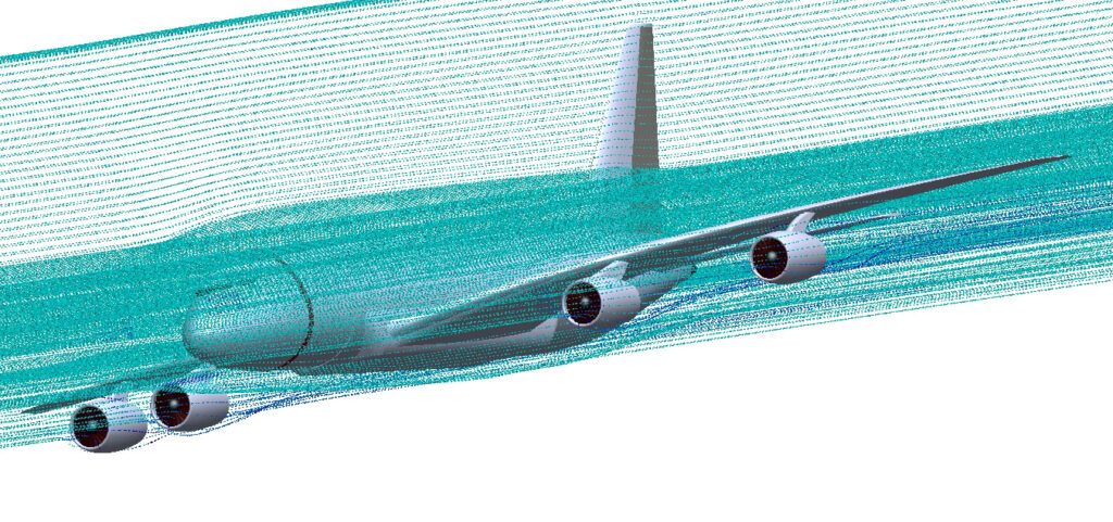
Velocity contours reveal acceleration zones, stagnation regions, recirculation, wakes, jets, and other important flow structures. Meanwhile, streamlines and vector plots help engineers understand how the fluid moves around the geometry.
Pressure fields provide another essential part of the aerodynamic picture. When flow approaches a body, it decelerates near a stagnation region and typically produces relatively high static pressure. Conversely, flow acceleration around curved surfaces can create lower-pressure regions. The resulting pressure distribution contributes directly to aerodynamic forces.
Consider an airfoil. Pressure differences between its surfaces contribute to lift, while pressure forces and viscous shear both contribute to drag. Therefore, engineers should not evaluate lift and drag coefficients alone. Instead, they should also examine the flow structures and surface distributions responsible for those integrated values.
The same principle applies to road vehicles. A simulation may predict excessive drag, but the drag coefficient alone does not identify the best design modification. Pressure contours, surface coefficients, streamlines, wake plots, and force decomposition can reveal whether the major losses originate from frontal pressure, underbody flow, wheel regions, appendages, or a large separated wake.

Boundary Layers, Flow Separation, and Aerodynamic Efficiency
Near a solid surface, viscosity creates a boundary layer in which velocity changes rapidly from the no-slip condition at the wall toward the external flow velocity.
Although this region may occupy only a small portion of the computational domain, it strongly influences skin-friction drag, separation, heat transfer, and wake development.
An adverse pressure gradient can slow the boundary layer. If the near-wall flow loses enough momentum, the boundary layer may separate from the surface. Separation can create recirculation regions, increase pressure drag, generate vortical structures, and cause unsteady aerodynamic loading.
Consequently, aerodynamic optimization often focuses on controlling boundary-layer development and delaying or managing separation.
For example, engineers may modify surface curvature, leading-edge and trailing-edge geometry, vehicle rear-end shape, diffuser angles, fairings, spoilers, winglets, or other flow-control devices.
However, the best modification depends on the engineering objective. A geometry that reduces drag at one operating condition may compromise stability, lift, downforce, or performance at another condition. Therefore, engineers should evaluate the relevant operating envelope instead of optimizing a design around one CFD result.
Turbulence strongly influences many of these phenomena. Readers who want to explore the underlying modeling considerations can see Introduction: Why Turbulent Models Matter in CFD.
CFD Drag Analysis: Connecting Flow Structures to Engineering Decisions
For many applications, CFD drag analysis provides one of the clearest links between simulation and engineering value.
Aerodynamic drag commonly includes pressure and viscous contributions. Their relative importance changes with geometry, Reynolds number, surface characteristics, and flow regime.
For a streamlined body, engineers may focus on minimizing separation while maintaining favorable pressure recovery. In contrast, bluff bodies naturally generate substantial separated wakes. Therefore, optimization may focus on controlling the size, strength, or organization of those wakes.
Imagine that engineers compare three rear-end geometries for a road vehicle. Design A produces a relatively small local pressure penalty but develops a broad separated wake. Design B reduces the wake size but creates additional losses elsewhere. Design C produces more favorable pressure recovery and ultimately achieves the lowest total drag.
A simple comparison of geometry would not reveal this mechanism. CFD can help expose it.
This raises an important engineering question: if one design produces a lower drag coefficient, do you know which physical change actually caused the improvement?
If the answer is no, engineers may need further flow analysis. Reliable optimization requires an understanding of the physical mechanism behind the numerical result rather than simply selecting the smallest number from a results table.
Lift, Downforce, and Aerodynamic Balance
Drag reduction does not always represent the only design objective. Aircraft require adequate lift and favorable lift-to-drag performance. Racing vehicles may require substantial downforce while controlling drag. Wind-sensitive structures may need reduced aerodynamic loading or improved stability.
Therefore, engineers frequently evaluate several quantities simultaneously, including lift coefficient, drag coefficient, pitching moment, pressure distribution, center of pressure, and aerodynamic efficiency.
For aircraft, the lift-to-drag ratio provides an important measure of aerodynamic efficiency. Meanwhile, automotive applications may require engineers to balance total drag against front-to-rear downforce distribution, stability, and cooling requirements.
Because these objectives can conflict, aerodynamic optimization usually involves engineering trade-offs rather than one universally optimum geometry.
For example, increasing the angle of an aerodynamic element may generate additional downforce while simultaneously increasing drag. Engineers must therefore determine whether the additional aerodynamic force justifies the efficiency penalty.
Flow separation can change this balance dramatically. The stall process in aerodynamics provides a particularly important example because extensive separation can fundamentally alter lift, drag, and aerodynamic stability.
Wakes and Vortices: Looking Beyond Surface Results
Some of the most important aerodynamic information appears downstream rather than directly on the surface.
Separated shear layers can form complex wakes, while wing tips, sharp edges, rotating components, and flow-control devices may generate strong vortices. These structures can increase energy losses, induce aerodynamic forces, create noise, influence downstream components, and produce unsteady loading.
For example, wing-tip vortices contribute to induced drag on finite wings. Similarly, a large vehicle wake can contribute substantially to pressure drag. Engineers can use vorticity fields, Q-criterion or related vortex-identification methods, velocity slices, and streamline visualizations to investigate these structures.
However, visualization should support quantitative analysis rather than replace it. Engineers should connect observed flow structures with forces, moments, pressure coefficients, velocity profiles, or other measurable quantities.
The effect of Reynolds number also deserves attention because it influences boundary-layer behavior, transition, separation, and wake characteristics. A useful visual example appears in Fluid Flow Over a Cylinder: CFD Reynolds Number Visualization. Engineers can also use the Reynolds Number Calculator when they need a quick estimate of this fundamental dimensionless parameter.
Computational Domain Size and Boundary Conditions
The quality of a CFD result depends partly on how engineers represent the environment surrounding the geometry.
For external aerodynamic simulations, computational boundaries should sit far enough from the body to avoid significantly influencing the solution. If a boundary lies too close, it can distort pressure fields, streamline curvature, blockage effects, or wake development.
Engineers must also define appropriate boundary conditions. Depending on the application, these may include freestream velocity, turbulence quantities, pressure outlets, symmetry boundaries, moving ground conditions, rotating wheels, wall roughness, or periodic boundaries.
For vehicle aerodynamics, for example, a stationary ground plane can produce different underbody flow from a moving-ground representation. Likewise, rotating wheels can substantially alter local flow around the wheelhouses and influence the downstream wake.
Aircraft simulations introduce other considerations. Engineers must define the angle of attack, freestream conditions, turbulence properties, operating pressure, and, for compressible flows, suitable thermodynamic conditions.
Therefore, a credible simulation should reproduce the physical operating conditions closely enough to answer the engineering question.
Near-Wall Mesh Resolution and Boundary-Layer Accuracy
Mesh quality strongly affects aerodynamic CFD because important velocity gradients occur close to solid surfaces.
Engineers often use inflation or prism layers to resolve the boundary layer efficiently. They should select the first-cell height and near-wall resolution according to the turbulence model and wall-treatment strategy.
The dimensionless wall distance, commonly expressed as y+, provides an important indicator of near-wall mesh resolution. However, engineers should not treat one target y+ as a universal mesh-quality criterion. The appropriate range depends on the turbulence formulation, Reynolds number, wall treatment, and objectives of the analysis.
Furthermore, engineers should maintain suitable cell growth through the boundary layer and provide enough layers to represent its development. Poor near-wall resolution can alter wall shear stress, separation location, pressure recovery, and ultimately predicted aerodynamic forces.
Mesh refinement also deserves attention away from the walls. Engineers may need finer cells around leading and trailing edges, narrow gaps, wakes, shear layers, vortices, and regions with strong pressure or velocity gradients.
Choosing an Appropriate Turbulence Model
Most industrial aerodynamic simulations involve turbulent flow. Therefore, turbulence-model selection becomes one of the most important modeling decisions.
Reynolds-Averaged Navier–Stokes, or RANS, models remain common because they provide a practical balance between computational cost and engineering usefulness. Depending on the flow, engineers may consider k-ε variants, k-ω formulations, SST k-ω, Spalart–Allmaras, or other appropriate formulations.
No turbulence model performs best for every aerodynamic problem.
For example, flows with strong adverse pressure gradients and separation may place different demands on a turbulence model than attached boundary-layer flows. Moreover, the predicted results depend not only on the selected model but also on near-wall resolution, numerical schemes, boundary conditions, and the physical assumptions behind the simulation.
NASA maintains an authoritative Turbulence Modeling Resource that provides turbulence and transition model information together with verification and validation cases. Engineers can use such benchmark resources to understand model behavior instead of treating turbulence selection as a software-default decision.
For applications where large unsteady structures dominate performance, engineers may consider scale-resolving approaches such as Large Eddy Simulation (LES) or hybrid RANS-LES methods. These methods can provide substantially more information about transient wake dynamics. However, they usually demand much greater computational resources.
Therefore, engineers should select the turbulence approach according to the expected physics, available computational resources, and required level of accuracy.
Mesh Independence and Numerical Convergence
A converged solver does not automatically produce an accurate aerodynamic prediction.
Engineers should distinguish iterative convergence from grid convergence. Residual reduction and stable monitored quantities can indicate that numerical iterations have approached a solution on a particular mesh. However, that solution may still depend strongly on spatial discretization.
A mesh-independence or grid-convergence study addresses this issue.
Engineers can systematically refine the mesh and compare quantities such as drag coefficient, lift coefficient, pressure coefficients, separation location, or velocity profiles. If the quantities of engineering interest change substantially as the mesh becomes finer, the original mesh may not provide sufficient resolution.
At the same time, convergence assessment should extend beyond residuals. Engineers can monitor drag, lift, mass conservation, pressure differences, or other application-specific quantities throughout the solution.
NASA’s CFD Verification and Validation tutorial provides useful engineering guidance on iterative convergence, solution consistency, spatial grid convergence, and temporal convergence.
Therefore, professional CFD simulation services should assess numerical sensitivity when the engineering decision requires it instead of reporting results from one arbitrary mesh.
Even a mesh-independent solution can disagree with reality if the physical models do not represent the actual flow adequately.
Validation Against Experimental and Wind-Tunnel Data
Validation addresses this problem by comparing computational predictions with experimental observations. Depending on the project, engineers may compare CFD results with wind-tunnel measurements, published benchmark cases, surface-pressure measurements, force coefficients, velocity profiles, particle image velocimetry data, or full-scale tests.
Verification and validation address different questions. Verification examines numerical and implementation aspects of the computational solution, whereas validation assesses how well the computational model represents physical reality for its intended application.
This distinction matters greatly in professional CFD analysis services. A simulation can converge numerically and still provide an inadequate representation of the actual flow.
Consequently, validation should focus on quantities that matter to the design decision. If engineers use CFD to predict vehicle drag, validation of drag and major wake characteristics carries more value than agreement in an unrelated variable.
The ASME V&V 20 standard provides a formal framework for verification and validation in computational fluid dynamics and heat transfer. Therefore, it offers a useful reference when simulation credibility and uncertainty become important parts of engineering decision-making.
Practical Applications of Aerodynamic CFD Simulation
Engineers apply aerodynamic CFD simulation across a wide range of industries.
In automotive engineering, CFD can evaluate vehicle drag, lift, underbody flow, wheel aerodynamics, cooling-air interactions, spoilers, diffusers, and wake behavior. Teams can then compare design variants before building full-scale prototypes.
In aerospace engineering, simulations can investigate airfoils, wings, fuselages, nacelles, control surfaces, and complete aircraft configurations. Engineers may examine lift, drag, moments, separation, stall behavior, and shock waves in compressible cases.
Wind engineering provides another important application. CFD can help engineers assess wind loading on buildings, flow around structures, pedestrian-level wind conditions, and interactions between nearby structures.
The same fundamental methods also extend into building engineering. For example, CFD analysis of building ventilation and HVAC systems uses velocity, pressure, turbulence, and thermal fields to investigate airflow performance in the built environment.
Likewise, industrial equipment often contains external-flow components that benefit from aerodynamic analysis. Enclosures, cooling systems, exposed equipment, rotating machinery, and transport systems can all experience performance losses or structural loads because of external flow.
Comparing Aerodynamic Design Alternatives with CFD
One of CFD’s strongest advantages appears when engineers need to compare several design alternatives under consistent operating conditions.
Suppose an engineering team develops five candidate geometries. Instead of manufacturing every version, the team can create a controlled simulation workflow and compare each design using consistent domain dimensions, boundary conditions, numerical schemes, turbulence treatments, and performance metrics.
Engineers can then compare:
- drag and lift coefficients;
- lift-to-drag ratios;
- surface-pressure distributions;
- separation locations;
- wake size and velocity deficit;
- vortex structures;
- aerodynamic moments;
- local wall shear stress;
- pressure recovery;
- performance across several operating conditions.
However, engineers should maintain numerical consistency between cases. If each design uses substantially different meshing strategies or convergence criteria, numerical differences may contaminate the comparison.
For this reason, systematic CFD workflows often provide greater design value than isolated simulations. They also allow engineers to combine simulation with engineering judgment during simulation-driven product development.
Where CFD Optimization Has Limitations
CFD offers substantial insight, but it does not automatically identify an optimum design.
First, simulation results depend on modeling assumptions. Turbulence models approximate complex turbulent physics, while simplified geometry may omit important details. In addition, boundary conditions may not capture every aspect of real operating environments.
Second, an aerodynamic optimum often depends on several competing objectives. A lower-drag geometry may produce inadequate cooling. More downforce may increase drag. A design that performs well at one angle of attack may perform poorly at another. Furthermore, manufacturing constraints may make a numerically attractive geometry impractical.
Third, uncertainty remains part of computational engineering. Mesh resolution, discretization, turbulence modeling, experimental uncertainty, geometry tolerances, and operating-condition variations can all affect conclusions.
Therefore, engineers should use CFD to identify trends, understand physical mechanisms, compare alternatives, and support decisions. They should not treat every computed decimal place as equally meaningful.
CFD as a Design Tool, Not an Automatic Answer
Modern CFD software can generate impressive visualizations quickly. Nevertheless, reliable aerodynamic optimization still requires engineering judgment.
Geometry preparation can remove physically important features. An inadequate computational domain can influence the solution. A coarse mesh can shift separation points. An unsuitable turbulence model can misrepresent wake behavior. Incorrect boundary conditions can simulate the wrong operating environment. Finally, numerical convergence alone cannot prove physical accuracy.
Therefore, engineers should interpret CFD results within a structured process:
- Define the aerodynamic objective and quantities of interest.
- Identify the important physical mechanisms.
- Create a computational model appropriate for those mechanisms.
- Establish suitable boundary conditions and domain dimensions.
- Generate and assess the mesh, especially near critical surfaces.
- Select physical and turbulence models according to the expected flow.
- Check numerical convergence and conservation.
- Assess mesh sensitivity.
- Validate important predictions when suitable data exist.
- Compare design alternatives using both quantitative metrics and flow physics.
This approach turns simulation output into defensible engineering evidence.
Engineers, researchers, and students who want to strengthen these skills can also explore CFD Vision’s CFD Training and ANSYS Fluent support.
From CFD Results to Better Aerodynamic Designs
The greatest value of aerodynamic CFD simulation does not come from predicting one drag or lift coefficient. Instead, it comes from revealing the relationship between geometry, flow physics, and engineering performance.
Velocity and pressure fields show how the fluid responds to geometry. Boundary-layer analysis reveals where viscous effects and adverse pressure gradients become important. Separation and wake analysis identify sources of aerodynamic loss. Meanwhile, force and moment calculations translate these phenomena into measurable engineering performance.
Engineers can then modify geometry, rerun the analysis, and compare alternatives systematically. As a result, CFD can reduce unnecessary physical prototypes, focus wind-tunnel campaigns on the most promising concepts, and provide insight that measurements alone may not easily reveal.
However, trustworthy results require careful modeling, verification, validation, and engineering interpretation. CFD should complement engineering knowledge and experimental evidence rather than replace them.
CFD Vision provides professional CFD consulting and CFD simulation services for engineering projects that require detailed flow analysis, aerodynamic assessment, turbulence modeling, and simulation-driven design. You can also learn more about CFD Vision and its engineering approach.
If aerodynamic performance forms part of a wider engineering design challenge, explore our Product Development services to see how numerical simulation can support decisions from early concepts through design refinement.
Contact CFD Vision for expert CFD simulation services tailored to your aerodynamic analysis and engineering design requirements.