
Short answer: A CFD result is reliable when it has been verified (the equations are solved correctly: converged, mesh- and time-step-independent, conservative) and validated (the model matches measured or benchmark data for the quantities that drive your decision), and when its remaining uncertainty is stated. A converged solution with attractive contours is not, on its own, evidence of accuracy.
Computational Fluid Dynamics can reveal flow structures, pressure distributions, temperature fields and forces that experiments struggle to measure in detail. Before those predictions drive a design decision, however, they need CFD validation. A simulation can converge cleanly, produce convincing contours, and still be wrong.
Reliable CFD takes more than solving the governing equations. You need to know how well the numerical model represents the physical problem, and how numerical error, modeling assumptions, boundary conditions and input uncertainty affect the answer. That matters most when CFD supports product development, equipment optimization, thermal management, aerodynamic design or safety-related decisions, and it is why professional CFD simulation services should include verification and validation whenever prediction accuracy affects the outcome.
CFD Verification and CFD Validation Are Not the Same
The two terms are often used interchangeably, but they answer different questions.
| Verification | Validation | |
|---|---|---|
| Question | Are we solving the equations correctly? | Are we solving the right equations for this physical problem? |
| Typical checks | Iterative convergence, mesh and time-step independence, conservation | Comparison with experiments, field data, analytical or benchmark solutions |
| Main error source | Numerical (discretization, iteration, round-off) | Model-form (turbulence model, boundary conditions, geometry, material data) |
| Can be done without test data? | Yes | Only partly, through analytical or published benchmarks |
Suppose you model pressure loss through an industrial duct. A mesh independence study shows further refinement changes the predicted pressure drop by less than 1%. That strengthens numerical confidence but does not prove the model represents reality: the turbulence model, wall roughness, inlet conditions or geometry simplifications can still cause significant error. A credible assessment covers both, which is also what to look for when evaluating CFD consulting or CFD analysis services.
1. Start CFD Verification With Numerical Convergence
Before comparing CFD with experiments, make sure the numerical solution itself behaves properly. Residuals describe how the iterative solver is progressing, but falling residuals alone do not prove convergence. Monitor the physical quantities you actually care about, for example:
- pressure drop across a component;
- mass flow rate through an outlet;
- lift and drag coefficients;
- surface temperature;
- heat-transfer rate;
- pump head or torque;
- aerodynamic forces.
If residuals fall while a key quantity keeps oscillating or drifting, the solution is not finished. Convergence criteria should also match the purpose: a variation that is harmless in an early concept study may be unacceptable when you need an accurate performance figure.
2. Perform a Mesh Independence Study
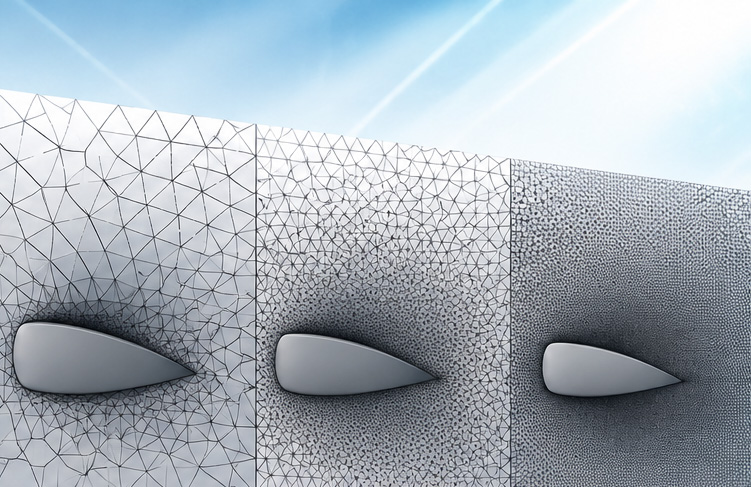
Mesh resolution is one of the largest sources of numerical error, because CFD solves discretized equations and the mesh shapes the answer. A mesh independence study tracks how quantities of engineering interest change as the mesh is systematically refined. For example, three meshes might predict:
| Mesh | Predicted pressure drop | Change from previous mesh |
|---|---|---|
| Coarse | 118 Pa | – |
| Medium | 125 Pa | +5.9% |
| Fine | 127 Pa | +1.6% |
Do not judge this from total cell count alone. Refinement should target the regions that control the physics: boundary layers, wakes, jets, recirculation zones, shocks, interfaces, narrow passages and steep thermal gradients. For wall-bounded turbulent flow, near-wall resolution must also suit the turbulence treatment; a mesh built for wall functions may not suit a model that resolves the viscous sublayer. Our CFD mesh first-cell height (y+) calculator gives a quick starting estimate.
For higher-consequence studies, go beyond a qualitative check and estimate discretization uncertainty with systematic grid refinement, Richardson extrapolation or the Grid Convergence Index (GCI), using at least three meshes with a consistent refinement ratio.
3. Check Mass, Momentum, and Energy Conservation
CFD solves conservation equations, so conservation is a powerful diagnostic. In a steady flow without mass sources, mass in should closely match mass out; a significant imbalance points to incomplete convergence, unsuitable boundary conditions or mesh problems. Thermal simulations should likewise close their energy balance across inflow, outflow and wall heat transfer.
These checks often reveal problems that contour plots hide: a temperature field can look physically reasonable while the overall energy balance is off. Clients of professional CFD analysis services need quantitative answers such as pressure loss, temperature, heat-transfer rate, drag or flow split, not attractive images, so integrated quantities deserve the closest scrutiny.
4. Compare CFD Results With Experimental or Analytical Data
Comparison with reliable measurements is one of the strongest forms of validation. Depending on the application, useful reference data include:
- pressure measurements;
- velocity profiles;
- flow rates;
- temperature measurements;
- heat-transfer coefficients;
- lift and drag data;
- pump performance curves;
- published benchmark experiments.
Focus the comparison on quantities that matter for the decision. If CFD predicts the pressure distribution around a cylinder well but misses the separation point, it can still fail when the project needs drag or wake predictions. For simple cases, analytical solutions such as fully developed laminar pipe flow or pure conduction are valuable benchmarks for testing numerical behavior.
5. Test Boundary-Condition Sensitivity
Boundary conditions can influence predictions as strongly as numerical settings. Many inputs are only known within a range: inlet flow rate, ambient temperature, surface roughness, outlet conditions, turbulence intensity, heat flux or thermal contact resistance. A sensitivity study shows which of these actually move the answer.
If raising inlet turbulence intensity from 3% to 5% barely changes pressure drop, that input matters little for that output. If the same change shifts the heat-transfer prediction substantially, it needs a better specification. This also prevents false precision: reporting 127.36 Pa means little when uncertain inputs could move the result by 10 Pa. The most useful question in any CFD project is: which assumptions could change the engineering conclusion if they were slightly different?
6. Assess Turbulence and Physical Model Sensitivity
A numerically converged solution can still carry model-form error. Turbulence modeling is the classic example: k-ε, k-ω SST, Reynolds stress models and LES make different assumptions and resolve different levels of flow physics. Strong separation, swirl, transition, buoyancy, compressibility, rotation, conjugate heat transfer or multiphase effects all raise the stakes.
Choose physical models for the dominant physics, not because they are the software default. When model choice could change a design decision, comparing suitable alternatives provides useful evidence, although agreement between two models does not prove either is accurate. This is where experienced Computational Fluid Dynamics consulting adds most value: model selection needs an understanding of both the numerical method and the physics of the real system.
7. Examine Time-Step Independence for Transient CFD
Transient simulations add temporal discretization error. A time step that is too large can smooth rapid changes, shift oscillation frequencies, cut peak loads or suppress transient structures, so test whether a smaller step materially changes the outputs. For periodic flows, compare frequency, amplitude, mean forces or phase-dependent quantities; for thermal transients, compare heating rates and peak temperatures. Simulate enough physical time to wash out initialization effects before sampling results.
8. Quantify CFD Uncertainty Instead of Claiming Perfect Accuracy
No simulation reproduces reality perfectly. Uncertainty analysis aims for a defensible confidence range rather than a claim of exactness. Typical sources include:
- spatial and temporal discretization;
- iterative convergence;
- geometry simplifications;
- uncertain material properties;
- boundary-condition uncertainty;
- turbulence and other physical models;
- experimental measurement uncertainty.
Which source dominates depends on the application: mesh uncertainty in one aerodynamic calculation, uncertain heat generation in an electronics-cooling model, turbulence modeling in another project. A professional study identifies the uncertainties that could change the decision and investigates those. It also lets CFD consultants communicate the limits of a prediction honestly, explaining assumptions, sensitivity and confidence rather than presenting a single number as exact. The ASME V&V 20 standard provides a formal framework for this.
9. Validate the Quantities That Drive the Engineering Decision
Validation should match the intended use of the model. In a heat-exchanger study, agreement with measured inlet and outlet temperatures is useful evidence, but it does not validate local hot-spot predictions if those hot spots govern material life. Likewise, a pump simulation may predict overall head well while missing local cavitation. The model can then support one decision and be unsuitable for another.
Validation never makes a model universally correct; it establishes confidence for specific quantities, operating conditions and physical regimes. Define validation targets at the start of a project, not as a final box-ticking step. In product development, that means validating the quantities that decide whether one design genuinely outperforms another.
10. Document the CFD Validation Process
Reproducibility builds credibility. A professional CFD report should let another competent engineer understand how the model was built and checked. Depending on the project, it should record:
- geometry assumptions and simplifications;
- computational domain;
- mesh strategy and quality;
- near-wall treatment;
- solver and discretization schemes;
- turbulence and physical models;
- material properties;
- boundary and initial conditions;
- convergence criteria;
- mesh or time-step sensitivity;
- conservation checks;
- validation data and comparison metrics;
- important uncertainties and limitations.
This record matters most when results influence design changes, capital investment or regulatory decisions, and it is what separates engineering analysis from producing simulation images.
What Makes CFD Results Reliable Enough?
There is no universal error percentage that makes a simulation “validated”. The required confidence depends on the application, the available data, the project stage and the consequences of being wrong; a concept study and a safety-critical final design need different levels of evidence. Use this checklist:
CFD reliability checklist
- Has the numerical solution converged adequately?
- Has mesh independence been demonstrated or discretization error quantified?
- Does the solution satisfy the relevant conservation principles?
- Do experimental, analytical or benchmark data support the predictions?
- Are results robust to reasonable changes in uncertain boundary conditions?
- Are the physical models appropriate for the dominant flow and heat-transfer phenomena?
- Have the important uncertainties and limitations been identified?
- Does the validation evidence directly support the quantities used for the decision?
Frequently Asked Questions
What is the difference between CFD verification and validation?
Verification checks that the equations are solved correctly (convergence, mesh and time-step independence, conservation). Validation checks that the model represents the real system, by comparing with experiments or trusted benchmarks. You need both before relying on a result.
How many meshes do I need for a mesh independence study?
At least three systematically refined meshes, so that you can see the trend and, for important studies, estimate discretization uncertainty with Richardson extrapolation or the Grid Convergence Index. Two meshes show a difference but not whether the solution is converging.
What is an acceptable error for a CFD simulation?
There is no universal figure. Acceptable error depends on the decision the result supports, the project stage and the cost of being wrong. State the uncertainty for the quantities that matter instead of quoting a generic accuracy percentage.
Can a CFD model be validated without experimental data?
Only partly. Analytical solutions and published benchmark cases can validate the modeling approach for similar physics. Without data for the actual system, the honest description is a verified model with stated assumptions, not a validated one.
CFD Validation Turns Simulation Into Engineering Evidence
CFD delivers its greatest value when its predictions can be defended. Convergence, mesh independence, conservation checks, experimental comparison, boundary-condition and model sensitivity, and uncertainty analysis together turn CFD from a visualization tool into engineering evidence. The level of effort should match the project’s objectives and risk: a benchmark comparison and a systematic mesh study may be enough for some decisions, while others need dedicated experiments or formal uncertainty quantification.
For further reading, NASA’s CFD Verification and Validation material covers iterative convergence, solution consistency, spatial and temporal convergence, and comparison against accurate solutions.
Need results you can defend? CFD Vision provides CFD simulation services and CFD analysis services for design, performance assessment, optimization and product development, with verification and validation built into the scope. See how we run a CFD consulting project, browse our CFD simulation projects, or contact CFD Vision to discuss a validation strategy for your project. Professional CFD consulting should deliver confidence in the decision, not just a converged solution.
About the author: Dr Ryan Mozafari leads CFD Vision. He holds a PhD in thermal-fluid science from Macquarie University and has more than 10 years of experience applying CFD to industrial and academic problems. LinkedIn · Google Scholar