
Short answer: CFD lets you see inside a centrifugal pump before it is built: where energy is lost, where pressure drops low enough to risk cavitation, and whether the impeller and volute deliver the required head and flow. Used properly, it narrows the design to a candidate worth testing; the physical performance test remains the final validation.
The Role of CFD Simulation in Centrifugal Pump Design
Centrifugal pumps run water treatment plants, process lines, mining circuits and oil and gas facilities, often for decades. Because they run continuously, small hydraulic losses turn into large energy bills, and a design that performs well at its best efficiency point can still suffer from recirculation, vibration or cavitation at other duty points. Computational Fluid Dynamics (CFD) simulation resolves the flow through the impeller and volute, so engineers can understand why a pump performs as it does and change the geometry before cutting metal.
At CFD Vision, we provide CFD simulation services for pump design and performance assessment, from early hydraulic concepts to troubleshooting pumps already in service.
Case Study: Designing a High-Performance Centrifugal Pump
In one of our projects, we developed a centrifugal pump for a water application with the following duty:
| Design parameter | Value |
|---|---|
| Fluid | Water |
| Design flow rate | 2,200 m³/h (≈0.61 m³/s) |
| Design head | 60 m |
| Hydraulic power (ρgQH) | ≈360 kW |
| Main components modeled | Impeller, volute and connecting passages |
At this scale, efficiency is money. With roughly 360 kW of hydraulic power and an overall efficiency in the region of 80%, each percentage point of efficiency is worth around 5 kW of shaft power, every hour the pump runs.
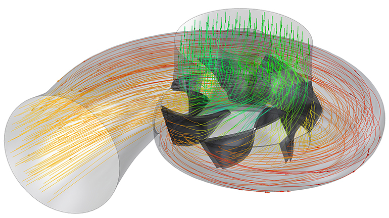
The project followed four steps:
- Building the 3D model. We created the impeller, volute and flow passages in detail, because blade angles, tongue clearance and passage areas control both head and losses.
- Simulating the internal flow. A rotating-frame CFD model resolved velocity, pressure and turbulence through the pump, showing how the flow enters the impeller eye, leaves the blades and diffuses in the volute.
- Checking performance against the duty. We calculated head and flow from the simulation to confirm the design could meet the 60 m, 2,200 m³/h target, and used the flow field to locate avoidable losses.
- Refining the geometry. We adjusted blade angles and the volute shape to reduce energy losses and improve the overall hydraulic performance before manufacturing.
A note on terminology: this kind of CFD check is often called “pump validation”, but strictly it is a design verification against targets. Full validation compares the CFD prediction with a measured performance curve. Our guide to CFD validation and simulation reliability explains the difference and why it matters.
What CFD Reveals Inside a Pump
Most pump problems have a visible signature in the flow field. The table below links common issues to what engineers look for in the CFD results and the design levers that usually address them.
| Problem | What CFD shows | Typical design levers |
|---|---|---|
| Cavitation risk | Regions near the blade leading edge where static pressure approaches vapour pressure | Inlet blade angle, eye diameter, leading-edge profile, suction conditions |
| Low efficiency | Separation on blades, poor diffusion in the volute, high loss in passages | Blade outlet angle and number, volute area distribution, passage shape |
| Part-load instability | Recirculation at the impeller inlet or outlet at reduced flow | Inlet geometry, blade loading, operating range |
| Vibration and noise | Pressure fluctuations near the volute tongue (transient simulation) | Tongue clearance and shape |
| Head shortfall | Integrated head below target at the design flow | Impeller diameter, blade outlet angle, slip |
Benefits of CFD Simulation in Pump Design
- Targeted efficiency gains: loss mechanisms are located, so changes go where they matter rather than being guessed.
- Performance across the curve: simulating several flow rates shows how the pump behaves away from the design point, not just at it.
- Fewer prototypes: weak concepts are rejected virtually, and physical testing is reserved for the strongest design.
- Insight tests cannot give: a test rig measures head, flow and power; CFD shows the flow structures that produce those numbers.
CFD Consulting for Pump Simulation
At CFD Vision, our CFD consulting and analysis services for pumps typically include:
- CFD simulation of pump performance at the design point and across the operating range;
- comparison of predicted head and efficiency with duty requirements or measured curves;
- cavitation-risk assessment and geometry optimization of impeller and volute;
- troubleshooting of in-service pumps with low efficiency, noise or damage.
Whether you need to design a new pump or diagnose an existing one, our CFD consultants tailor the model to the decision you need to make. For water utilities, mining operations and process plants, we provide CFD consulting across Australia from our Sydney base. Turbulence and rotating-machinery modeling choices matter here; see why turbulence models matter in CFD for background.
Frequently Asked Questions
Can CFD predict pump cavitation?
Single-phase CFD identifies regions where pressure falls towards vapour pressure, which flags cavitation risk. Predicting the extent of cavitation and its effect on head requires a cavitation (multiphase) model and, ideally, comparison with NPSH test data.
Does CFD replace pump performance testing?
No. CFD reduces the number of designs that need testing and explains the results, but a measured performance curve remains the final check of head, efficiency and power.
Should a pump be simulated at one operating point or several?
Several. Pumps rarely run only at their design point, and problems such as recirculation and cavitation often appear at part load or high flow. Simulating a range of flow rates builds a predicted performance curve.
Working on a pump design or a pump that underperforms? Contact CFD Vision to discuss a CFD simulation of your pump, or browse our CFD simulation projects. Beyond pumps, we apply the same methods through our product design services, and our CFD Teaching and academic CFD mentorship programs help engineers and researchers build independent simulation skills, understanding the physics and numerical methods behind the model, not just the software workflow.
About the author: Ryan Mozafari leads CFD Vision. He holds a PhD in thermal-fluid science from Macquarie University and has more than 10 years of experience applying CFD to industrial and academic problems. LinkedIn · Google Scholar