
Every industry that moves a fluid, sheds heat, or fights drag eventually runs into the same wall: physical testing alone cannot explore enough design options fast enough. This is where CFD simulation earns its place on the engineering desk, not as a rendering tool that produces pretty flow pictures, but as a predictive method that tells engineers how a design will actually perform before anyone cuts metal. Because a solver can evaluate flow, heat transfer, pressure distribution, and aerodynamic forces on a laptop overnight, teams can compare dozens of geometries in the time it once took to build a single prototype.
This article looks past the usual “CFD is used in aerospace, automotive, and energy” summary. Instead, it walks through the actual engineering problem in several sectors, the modeling approach an engineer would choose, the outputs that matter, and the design decision that follows. Along the way, it also covers where simulation runs into limits, because credible CFD analysis depends as much on discipline as on software.
From Physical Prototypes to Predictive Engineering
A wind tunnel test, a thermal chamber run, or a flow bench measurement answers one question about one geometry at one operating point. A well-built CFD model, on the other hand, can sweep across geometry variants, flow rates, and boundary conditions once the setup is validated. Consequently, engineers use simulation not to replace testing but to narrow the design space before committing to it, saving both time and tooling cost.
Three outputs recur across almost every industrial application:
- Velocity and pressure fields, which reveal separation, recirculation, and pressure losses
- Temperature distributions, which flag hotspots, thermal gradients, and cooling shortfalls
- Integrated forces and coefficients, such as lift, drag, or pressure drop, which feed directly into performance targets
Once an engineer trusts these outputs, the model becomes a decision-making tool rather than a visualization exercise.
Aerospace: Managing Separation and Stall Before the Wind Tunnel
Aircraft and turbine designers face a recurring risk: flow separation. If a wing, nacelle, or compressor blade separates earlier than intended, lift drops, drag rises, or stage efficiency collapses. Because separation is sensitive to Reynolds number, surface curvature, and turbulence behavior, engineers rely on Reynolds-Averaged Navier-Stokes models, paired carefully with an appropriate turbulence closure, to predict where and when it happens.
The resulting surface pressure distribution and skin friction plots let an aerodynamicist identify the exact region where flow starts to detach, then adjust camber, twist, or fillet geometry in response. Our related articles on the stall process in aerodynamics and aerodynamic performance optimization walk through this workflow in more depth. NASA’s public Turbulence Modeling Resource remains a useful reference for engineers who want to verify a turbulence model against documented benchmark cases before trusting it on a new geometry.
Automotive and Electric Vehicles: Balancing Drag, Cooling and Battery Thermal Management
Vehicle programs juggle competing objectives at once. Lower drag improves range and top speed, yet the underbody and grille also need enough airflow to cool the powertrain or battery pack. In electric vehicles specifically, battery thermal management becomes a safety issue as much as a performance one, since uneven cell temperatures accelerate degradation and, in extreme cases, trigger thermal runaway.
Coupled flow-and-heat-transfer models let engineers evaluate underhood or under-pack airflow alongside external aerodynamics in a single study. As a result, a design team can compare a closed grille shutter against an open one, or evaluate a redesigned battery coolant channel, and see the tradeoff between drag coefficient and peak cell temperature before building either variant. Readers interested in the cooling side of this problem can also see our post on advanced CFD thermal management for heat control.
Energy and Turbomachinery: Optimizing Pumps, Turbines and Heat Exchangers
Pumps, compressors, and turbines convert energy through fluid motion, so even small inefficiencies compound into significant operating cost over a machine’s lifetime. Here, CFD modeling typically resolves the flow through the impeller, volute, and diffuser sections, capturing losses from recirculation, cavitation risk, and secondary flow near blade tips.
Because these machines often run across a range of duty points rather than one fixed condition, engineers frequently simulate a full performance curve instead of a single operating point. This approach highlights where efficiency drops off away from the design point, which then guides blade angle, clearance, or volute geometry changes. Our case study on optimizing pump design through CFD simulation and validation shows this process applied to a real impeller redesign.
HVAC and Buildings: Ventilation, Comfort and Energy Efficiency
Building services engineers face a different flavor of the same problem: low-speed, buoyancy-driven flow that must satisfy comfort, indoor air quality, and energy codes simultaneously. Because occupied spaces involve large geometries and long time scales, mesh strategy and boundary condition selection matter even more than in high-speed external aerodynamics.
CFD analysis of diffuser placement, stratification, and contaminant dispersion helps engineers avoid stagnant zones or short-circuiting between supply and return air, both of which waste energy and hurt comfort. Rather than guessing at duct or diffuser layout, a design team can test several configurations virtually and select the one that meets ventilation targets with the lowest fan energy. For a deeper look at this workflow, see building ventilation and HVAC systems optimization with CFD.
Electronics Cooling and Data Centers: Keeping Pace with Rising Heat Loads
Chip power density keeps climbing, and cooling has become a design constraint that shapes enclosure layout, not an afterthought bolted on at the end. Conjugate heat transfer models, which solve solid conduction and fluid convection together, let engineers predict junction temperatures on a populated board before it ever reaches a thermal chamber.
At the facility scale, the same modeling approach identifies hot aisle recirculation and underutilized cooling capacity in a data hall, which directly affects both reliability and energy bills. Because rack layouts and IT loads change frequently, this is an area where simulation earns its keep repeatedly rather than once per product cycle, as covered in our article on CFD simulations for data center cooling and energy savings.
Biomedical Applications: Modeling Flow Where Testing Is Difficult
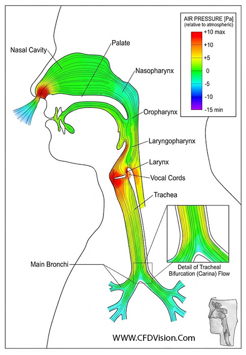
Cardiovascular devices, drug delivery systems, and respiratory airway studies present a harder validation problem, since in vivo measurement is often invasive or simply impossible at the required resolution. Even so, researchers have applied the same verification and validation discipline used in aerospace to biomedical flows. A well-documented example is the FDA nozzle benchmark study, which compared CFD predictions of velocity and shear stress against inter-laboratory experimental data to assess whether a given model could be trusted for a specific device evaluation, as reported in the peer-reviewed literature on the subject (see the study on the NIH PMC archive). This kind of rigor matters because shear stress predictions in blood-contacting devices connect directly to hemolysis risk, so an unvalidated model is not just inaccurate, it is potentially unsafe to rely on.
Why CFD Modeling Only Works When the Fundamentals Are Right
Here is a fair challenge worth asking before trusting any simulation result: if two engineers ran the same geometry through the same solver, would they get the same answer? Often, the honest response is no, because mesh quality, boundary condition assumptions, and turbulence model selection all shape the outcome as much as the geometry itself.
A few fundamentals separate a trustworthy CFD model from an expensive-looking guess:
- Mesh resolution near walls and in regions of high gradient, since an under-resolved boundary layer distorts drag, heat transfer, and separation predictions
- Boundary conditions that genuinely represent the physical inlet, outlet, and wall behavior, rather than convenient simplifications
- A turbulence or physics model chosen for the flow regime at hand, not simply the solver default
- A grid convergence study, which shows whether the solution has actually stabilized as the mesh refines
- Validation against experimental or field data wherever it exists, following an established framework such as the ASME V&V 20 standard
Our earlier article, why turbulence models matter in CFD, expands on how model choice alone can shift results by a meaningful margin. Skipping these steps does not make CFD simulation faster; it makes the output unreliable, which defeats the purpose of running the analysis at all.
From Analysis to Action: How CFD Reduces Development Iterations
The real payoff of CFD modeling is not the color contour plot, it is the decision that follows it. Once a model earns trust through verification and validation, engineers can screen far more design alternatives than a test program would allow, catch weaknesses early enough to fix them cheaply, and reserve physical testing for final confirmation rather than open-ended exploration. Meanwhile, simulation and experiment work best together rather than as substitutes for one another: test data anchors the model, and the model then extends insight to conditions or geometries that were never physically tested at all.
Emerging tools are extending this further. Surrogate models and machine-learning-assisted workflows, discussed in our post on AI-driven CFD simulation, now help engineers explore larger design spaces without rerunning a full solver every time, though the underlying physics still needs the same verification discipline. For a broader view of how this fits into the development timeline, see CFD in product development, from engineering concept to simulation-driven design.
Suggested image: a side-by-side contour plot showing airflow separation on a baseline versus optimized wing profile. Alt text: “CFD simulation comparison of airflow separation on baseline and optimized wing geometry.”
Suggested image: a conjugate heat transfer plot of a populated circuit board. Alt text: “CFD analysis of junction temperature distribution on an electronics cooling board.”

Where This Leaves Your Project
CFD simulation earns its value when it changes a real engineering decision, not when it produces a report nobody acts on. Whether the question involves separation on a wing, battery temperature in an EV pack, pump efficiency across a duty cycle, or airflow in a data hall, the same discipline applies: build the right model, mesh it properly, validate it against reality, and use the result to choose between design alternatives with confidence.
If your team is weighing a design decision that fluid flow or heat transfer will determine, CFD Vision’s CFD consulting services can help you scope the right modeling approach from the outset. Explore how we support product development programs from concept through validation, browse our CFD training courses if you want your own engineers to build this capability in-house, or get in touch through our about us page to discuss your project.
