
Short answer: CFD in product development means using simulation early, while the design still exists mainly as CAD, to compare concepts, find the physical cause of flow and thermal problems, and optimize geometry before prototypes are built. Instead of confirming a finished design, simulation-driven design uses CFD as a feedback loop that shapes each iteration, with physical testing reserved for the strongest candidates.
Product development starts with an engineering concept, but early design decisions largely decide whether that concept becomes an efficient, reliable and commercially successful product. CFD Product Design brings fluid flow, heat transfer, pressure and turbulence into those decisions before a company commits to manufacturing.
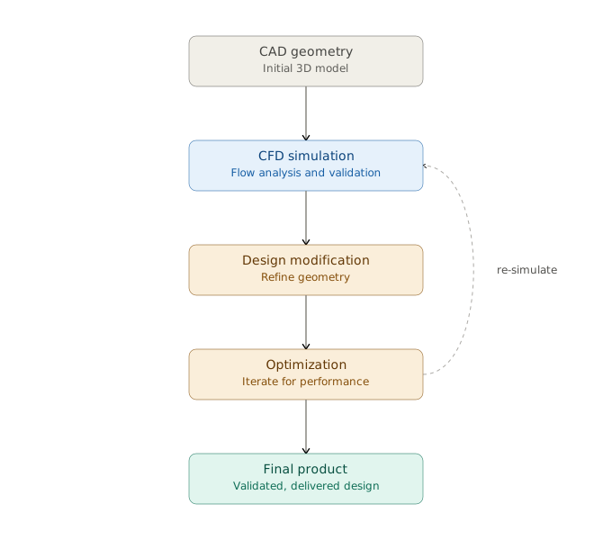
Traditionally, teams built prototypes first and used simulation later to investigate problems or check a nearly finished design. Modern computing has changed that. Computational Fluid Dynamics (CFD) can now guide geometry changes, compare competing concepts, expose performance limits and support optimization while engineers still have real freedom to change the design. For any product that handles fluids, thermal loads, ventilation, cooling, rotating equipment or aerodynamic flow, that shift can transform the development process.
Why CFD Product Design Should Begin Early
A physical prototype answers one question: how does this particular design perform? CFD answers a broader one: why does it perform this way, and what should we change? That difference is what matters during product development.
Take a compact electronic enclosure. The first concept may meet dimensional and manufacturing requirements, yet internal airflow creates recirculation around heat-generating components and local temperatures exceed limits. Found after prototyping, the fix means redesigning the enclosure, moving components, changing vents and building another prototype. Found through early CFD Design Analysis, it is solved while the geometry is still a CAD model. The same logic applies to:
- pumps and fans;
- heat exchangers;
- valves and manifolds;
- electronic cooling systems;
- HVAC equipment;
- aerodynamic components;
- ducts and ventilation devices;
- process equipment;
- thermal management systems;
- fluid distribution systems.
CFD creates the most design value before the geometry becomes expensive to change.
From CAD Geometry to CFD Design Analysis
A useful CFD study starts with an engineering question, not with software. Does a new manifold split flow evenly between its outlets? What is the pressure loss through a compact device? Will maximum component temperature stay below its limit? These objectives define the model: geometry preparation, domain, mesh, physical models, boundary conditions and the conservation equations to solve.
An attractive contour plot is not an engineering result. The simulation must tie directly to measurable design criteria, and key performance indicators should be agreed before alternatives are compared. Typical examples:
- pressure drop and mass-flow distribution;
- drag or lift;
- heat-transfer rate, maximum temperature and temperature uniformity;
- fan or pump performance;
- recirculation regions and flow separation;
- turbulence intensity and mixing quality.
CFD Design Optimization: Moving Beyond a Single Simulation
A single simulation identifies a problem; CFD Design Optimization shows how to improve the product. Consider a cooling channel with excessive pressure loss. CFD reveals that an abrupt transition causes separation and a large recirculation zone. Engineers can then vary transition angle, cross-section, curvature or internal features and compare candidates side by side:
| Design | Change from baseline | What CFD evaluates |
|---|---|---|
| A | Baseline geometry | Reference pressure drop, separation and heat transfer |
| B | Smoother transition | Reduction in separation and recirculation |
| C | Larger or reshaped cross-section | Lower pressure loss, effect on velocity and heat transfer |
| D | Added internal features | Heat-transfer gain versus extra pressure drop |
| E | Combined changes | Best balance of thermal and hydraulic performance |
Real products rarely have a single objective. More airflow may improve cooling while raising pressure loss, fan power and noise; more heat-transfer area may improve thermal performance at the cost of size and manufacturing complexity. Effective CFD optimization therefore needs engineering judgment, because the mathematically best flow solution is not always the best commercial product.
Virtual Prototyping Can Reduce Expensive Design Iterations
Physical testing remains essential, but not every idea needs to be manufactured. Virtual Prototyping screens concepts computationally so only the most promising reach the test bench. With eight candidate geometries for a new fluid-handling component, a team can use CFD to compare their main flow characteristics, reject weak concepts, refine the best and manufacture only a few optimized prototypes.
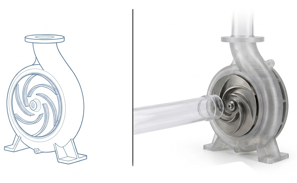
Simulation and testing complement each other: simulation gives detailed access to every variable in the domain, while experiments provide the physical evidence to evaluate the model and confirm performance. NASA’s verification and validation guidance separates the two ideas clearly: verification checks that the numerical solution behaves correctly, and validation checks how well it represents physical reality. ASME V&V 20 provides a framework for assessing CFD and heat-transfer accuracy against experimental data while accounting for uncertainty. For background, see NASA’s CFD Verification and Validation overview and ASME V&V 20 for CFD and heat transfer.
Simulation-Driven Design Creates an Engineering Feedback Loop
The greatest benefit comes when simulation feeds directly into design decisions. A Simulation-Driven Design workflow typically runs:
- Define product requirements and performance targets.
- Develop the initial CAD concept.
- Identify the relevant fluid and thermal physics.
- Build an appropriate CFD model.
- Evaluate the baseline design.
- Identify the physical causes of performance limitations.
- Modify the geometry or operating conditions.
- Compare alternative designs.
- Optimize the most promising concept.
- Validate critical predictions where appropriate.
- Finalize the design for manufacturing.
The loop often repeats several times. The CFD engineer’s job is not just to compute a flow field but to explain why a pressure loss occurs, why a hot spot develops, why flow separates or why one branch starves. Those insights drive the next iteration, and that feedback loop is where CFD’s commercial value lies.
What Happens When Several Design Objectives Conflict?
Suppose a company must redesign a compact heat exchanger to deliver 15% more heat transfer, without a significant rise in pressure drop and within the same installation volume. Simply maximizing heat transfer fails: aggressive flow-disturbing features raise the heat-transfer coefficient but can sharply increase hydraulic resistance. CFD compares velocity and temperature fields, pressure loss, local heat transfer and recirculation across candidate geometries, so the team can pick the best thermal-hydraulic balance rather than the best single number.
For preliminary estimates, CFD Vision’s Nusselt Number Calculator, Reynolds Number Calculator, Heat Transfer Calculator and Heat Exchanger Calculator are useful starting points. For more advanced thermal applications, see Advanced CFD Thermal Management Solutions for Heat Control.
Choosing the Right Physics for CFD Product Design
CFD is only as useful as its physical model. Simple internal flows may need little more than pressure loss and velocity distribution; complex products often need more:
| Physics | When it matters |
|---|---|
| Turbulence modeling | Most industrial flows; model choice must suit the flow and required accuracy |
| Conjugate heat transfer | Electronics, heat exchangers and cooling systems where solid conduction and fluid convection interact |
| Multiphase flow | Pumps, separators, reactors and sprays with gas-liquid, liquid-solid, free-surface, cavitating or dispersed flow |
| Rotating machinery | Fans, pumps, compressors and turbines with rotating and stationary domains |
| Transient flow | Pulsating flow, vortex shedding, start-up, moving parts and time-varying thermal loads |
For more on turbulence, see Introduction: Why Turbulent Models Matter in CFD; for rotating machinery in practice, see Optimizing Pump Design Through CFD Simulation and Validation. More complex physics does not automatically make a better model: use the fidelity needed to answer the design question reliably.
Mesh Quality and Numerical Accuracy Still Matter
Simulation-driven engineering only works when the numbers are dependable. A coarse mesh can miss boundary layers, jets, wakes, thermal gradients or separation; an unnecessarily fine one burns computing time without improving the decision. Refine strategically, and check iterative convergence, conservation, spatial convergence and, for transient cases, time-step independence whenever they affect the quantities of interest. Our guide to CFD verification and validation covers these checks in detail. The aim is not more cells but enough resolution to compare designs dependably.
CFD Design Analysis Should Focus on Decisions, Not Pictures
Streamlines, pressure contours and temperature maps help engineers understand complex physics, but product development needs quantitative conclusions. A useful engineering report answers:
- Which design produces the lowest pressure loss?
- Where does the flow separate?
- What causes the thermal hot spot?
- How uniformly does the system distribute fluid?
- Which geometry improves performance?
- How sensitive is the result to operating conditions?
- What design change should be investigated next?
Translating simulation results into engineering recommendations is what separates CFD engineering from CFD visualization, and it is what effective CFD consulting should deliver.
Connecting CFD With the Wider Product Development Process
CFD works best as part of a wider workflow that links CAD, hand calculations, CFD, structural analysis, optimization, prototype testing and manufacturing. An aerodynamically superior shape may not be manufacturable; a cooling fix may need extra material, space or fan power. CFD specialists therefore need to work closely with mechanical, thermal and product engineers and with manufacturing. Companies that want this integrated approach can explore CFD Vision’s Product Development services, where simulation supports decisions from early concept to design refinement.
When Should a Company Introduce CFD Into Product Development?
| Stage | What CFD contributes |
|---|---|
| Concept development | Reveals whether an architecture has fundamental flow or thermal limitations |
| Design comparison | Ranks competing concepts against performance targets |
| Optimization | Refines dimensions, shapes, flow paths, cooling layouts or operating conditions |
| Verification and validation | Checks the mature design against requirements and available measurements |
Companies should not automatically wait until the final design stage to request CFD Simulation Services. The earlier the simulation, the more freedom there is to act on the results.
Frequently Asked Questions
What is simulation-driven design?
It is a development approach in which simulation guides design choices from the concept stage, rather than only checking a finished design. CFD results feed back into each iteration of the geometry.
Does CFD reduce the number of prototypes?
Usually, yes. Weak concepts can be rejected virtually and the remaining designs refined before manufacture, so fewer physical prototypes are needed. Testing is still required to validate the final design.
What does a company need to provide for a CFD product study?
Typically CAD geometry, operating conditions (flows, temperatures, heat loads), material data, performance targets and any available test data. Clear targets matter most, because they define what the simulation must answer.
From CFD Simulation Services to Better Products
CFD has evolved from a specialist analysis method into a practical product-development tool. Used early, it exposes weaknesses before manufacturing, explains the physics behind performance problems, compares alternatives systematically and focuses testing on the strongest concepts. Simulation alone does not create a better product, though: engineers still have to ask the right questions, choose appropriate models, check numerical accuracy, interpret the physics and turn results into practical design changes. That combination turns CFD from a final verification exercise into Simulation-Driven Design.
Developing a product where airflow, liquid flow, cooling or heat transfer affects performance? Explore CFD Vision’s Product Development and CFD Simulation Services, see how we run a CFD consulting project, or browse our CFD simulation projects. Contact CFD Vision for expert CFD consulting tailored to your product development project.
About the author: Dr Ryan Mozafari leads CFD Vision. He holds a PhD in thermal-fluid science from Macquarie University and has more than 10 years of experience applying CFD to industrial and academic problems. LinkedIn · Google Scholar