
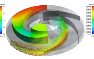
CFD investigation of a centrifugal pump impeller identified where hydraulic losses originate in the blade passages, and provided design insight for improving head generation and efficiency.
Sector
Pumping systems
Client
Industrial pump manufacturer
Flow type
Rotating turbulent liquid flow
Project Snapshot
Challenge
Impeller geometry controls how the liquid gains energy between the eye and the blade exit. Incidence losses at the blade leading edges, flow separation and uneven blade loading reduce head and efficiency, and they are hard to locate from performance tests alone.
Approach
A 3D rotating-frame CFD model resolved the velocity and pressure fields through the impeller passages. Predicted performance was checked against available pump data, and blade loading and passage flow were examined to locate the main sources of hydraulic loss.
Key Findings
- Pressure rose progressively along the passages, with the strongest blade loading concentrated toward the trailing edge.
- Flow incidence at the blade leading edges created local low-pressure regions, which are the most likely sites for losses and cavitation onset.
- Recirculation on the suction side of the blades reduced the effective passage area, which pointed to blade angle and passage shape as the key parameters for improving efficiency.
Deliverables
Impeller pressure and velocity fields, blade-loading assessment, identification of loss regions and design recommendations for centrifugal pump development.
Working on a similar problem?
Explore our CFD consulting services and engineering simulation services, or send us your centrifugal pump or rotating equipment question.