
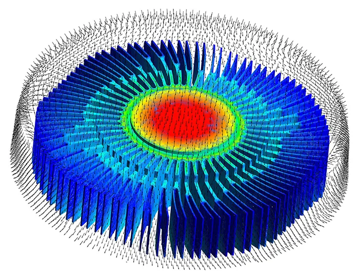
Airflow through the fins and temperature distribution across the heatsink
Thermal CFD analysis of a fan-cooled CPU heatsink, showing how air moves through the fins and where heat removal is limited.
Sector
Electronics
Client
Electronics hardware developer
Flow type
Forced convection, conjugate heat transfer
Project Snapshot
Challenge
As processor power rises, the heatsink must remove more heat in the same space. Air tends to bypass the fins or stagnate behind the fan hub, leaving parts of the heatsink underused.
Approach
A conjugate heat transfer model coupling fan-driven airflow with conduction through the base and fins, with the processor as the heat source and refined mesh in the fin passages.
Key Findings
- Temperature peaked in the base directly above the processor, with heat spreading limited by base thickness.
- Fin regions under the fan hub received much less airflow and contributed less to cooling.
- Fin spacing and airflow delivery, not just fin area, controlled overall cooling performance.
Deliverables
Temperature and airflow maps, underperforming fin regions and recommendations for fin geometry and airflow. More on advanced CFD thermal management and heat control.
Working on a similar problem?
Explore our CFD consulting services or send us your electronics cooling or heatsink question. Learn more about our computational fluid dynamics consulting in Australia.