
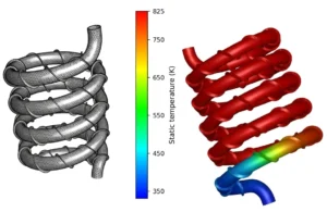
CFD simulation evaluated the trade-off between heat transfer and pressure drop in a spiral heat exchanger with spiral fins, identifying fin design features that improve thermal performance without excessive pumping cost.
Sector
Heat exchanger engineering
Client
Heat exchanger manufacturer
Flow type
Internal flow and conjugate heat transfer
Project Snapshot
Challenge
Spiral fins increase surface area and flow mixing, but they also add pressure drop and can create low-velocity zones that contribute little to heat transfer. The client needed to know whether the fin arrangement delivered a net performance gain and which geometric parameters mattered most for an optimum design.
Approach
A conjugate heat transfer model resolved the flow through the spiral passages and the heat conduction through the fins and walls. Heat transfer and pressure drop were assessed together, so that performance was judged by thermal gain per unit of pumping penalty rather than by heat transfer alone.
Key Findings
- The spiral fins induced secondary flow and repeated boundary-layer restart, raising local heat transfer coefficients compared with plain passages.
- Recirculation zones formed downstream of the fins. These added pressure drop but contributed little heat transfer, which showed where fin geometry could be refined.
- Fin pitch and height controlled the trade-off. Closer spacing increased pressure drop faster than it increased heat transfer, which points to an optimum spacing rather than “more fins is better”.
- Heat transfer weakened progressively along the spiral as the temperature difference decreased, so later sections are candidates for adjusted fin density.
Deliverables
Velocity, temperature and pressure fields, a heat transfer vs pressure drop assessment, and design recommendations for fin geometry and spacing.
Working on a similar problem?
Explore our CFD consulting services and engineering simulation services, or send us your your spiral heat exchanger or thermal system question.