
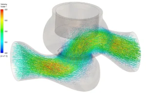
CFD simulation of a hydraulic control valve examined internal flow behaviour, pressure variation and local high-velocity regions through the valve passage.
Sector
Hydraulic systems
Client
Hydraulic equipment manufacturer
Flow type
Internal liquid flow
Project Snapshot
Challenge
A control valve must regulate liquid flow while avoiding undesirable separation, excessive local velocities and strong pressure losses. Internal geometry and opening position directly influence the flow path through the valve.
Approach
A 3D internal-flow model was used to evaluate velocity, pressure and recirculation through the valve at representative operating conditions.
Key Findings
- Flow accelerated through restricted portions of the valve passage.
- Pressure gradients were concentrated around the control region and downstream expansion.
- Separated and recirculating flow developed where the geometry caused abrupt changes in flow direction.
Deliverables
Valve flow-field assessment with pressure and velocity insight for hydraulic control-valve development.
Working on a similar problem?
Explore our CFD consulting services and engineering simulation services, or send us your your hydraulic control valve question.