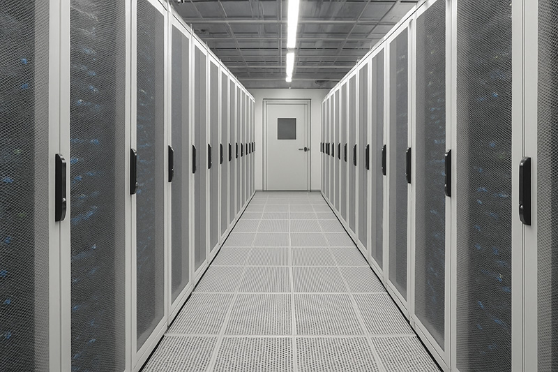
Modern data centers concentrate enormous computing capacity within relatively small spaces. As rack power densities increase, cooling systems must remove large and highly uneven heat loads while maintaining acceptable inlet conditions for sensitive IT equipment. Consequently, Data Center CFD Simulation has become an important engineering tool for identifying airflow and thermal problems before they threaten reliability or force operators to consume unnecessary cooling energy.
A data center can have sufficient nominal cooling capacity and still experience overheating. Poor airflow distribution, hot-air recirculation, cold-air bypass, pressure imbalance, and variations in rack power density can create local thermal problems that room-average measurements fail to reveal. Computational Fluid Dynamics addresses this limitation by predicting how air actually moves through the facility and how that airflow interacts with heat-generating equipment.
For organizations facing complex thermal-management problems, professional CFD simulation services can therefore provide much more than temperature visualization. A properly constructed model allows engineers to investigate the physical causes of cooling problems, compare alternative configurations, and determine how efficiently the cooling infrastructure supports the IT load.
Why Data Center Cooling Is an Airflow Problem
Every operating server converts most of its electrical input into heat that the cooling system must ultimately remove. However, supplying enough cooling capacity does not guarantee effective heat removal. The cooling system must also deliver sufficient conditioned air to the correct rack inlets and provide an effective path for heated exhaust air to return to the cooling equipment.
This requirement creates one of the central challenges in Data Center Airflow Analysis.
For example, a rack may receive less airflow than its servers demand. As a result, negative or unfavorable local pressure conditions can encourage hot exhaust air to return toward the rack inlet. Conversely, another part of the room may receive excessive cold air that bypasses the IT equipment entirely and flows directly toward the cooling-unit return.
Both situations waste cooling capacity.
The U.S. ENERGY STAR program emphasizes the same fundamental principle: conditioned supply air should reach IT equipment without mixing with hot exhaust, while exhaust air should return to cooling equipment without mixing with the cold supply stream. ENERGY STAR airflow-management guidance also identifies perforated-tile location, raised-floor leakage, subfloor obstructions, and recirculation as important contributors to data-center cooling performance.
Therefore, engineers should evaluate airflow distribution and heat transfer as a coupled system rather than treating cooling capacity as an isolated HVAC specification.
What Problems Can Data Center CFD Simulation Identify?
A detailed CFD model can reveal several problems that remain difficult to diagnose from isolated temperature sensors.
Hot Spots and Insufficient Rack Airflow
High-density racks can require substantially more airflow than neighboring equipment. If the local supply cannot satisfy that demand, server fans may draw warmer surrounding air toward their inlets.
CFD allows engineers to examine rack inlet temperatures at different heights rather than relying on one room temperature. This distinction matters because upper servers can experience significantly different thermal conditions from equipment near the bottom of the same rack.
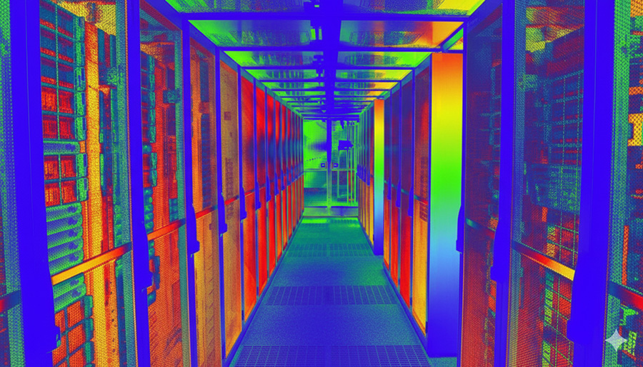
Temperature contours can reveal the resulting hot spots, while velocity vectors and streamlines help identify their aerodynamic cause.
Hot-Air Recirculation
Recirculation occurs when heated exhaust air reaches server inlets instead of returning efficiently to the cooling equipment. Gaps between racks, open rack units, poor aisle geometry, insufficient containment, and pressure imbalance can all contribute to this behavior.
The resulting temperature rise may encourage operators to reduce the cooling-system supply temperature. However, this response can increase energy consumption without correcting the underlying airflow problem.
Instead, CFD helps engineers trace the recirculation path and address its cause.
Cold-Air Bypass
Bypass creates the opposite problem. Conditioned air passes around the IT equipment and returns to the cooling units without absorbing the intended server heat load.
For example, excessive airflow through perforated tiles can supply more air than nearby racks require. Leakage through cable openings or poorly sealed raised floors can create similar losses.
Consequently, the facility may appear to have high cooling airflow while individual racks still suffer from insufficient supply.
Pressure Imbalance
Pressure distribution plays an important role in raised-floor data centers. The underfloor plenum must develop enough static pressure to distribute air through perforated tiles or grilles. However, cables, structural members, local flow resistance, and cooling-unit locations can produce highly nonuniform pressure.
A CFD pressure map can identify regions where insufficient plenum pressure limits tile airflow. Engineers can then modify tile placement, airflow resistance, fan operation, or underfloor obstructions instead of simply increasing total cooling capacity.
How Engineers Build a Data Center CFD Model
Reliable CFD Thermal Analysis starts with an appropriate representation of the physical facility. A model that looks visually detailed does not automatically produce accurate predictions. Instead, engineers must represent the mechanisms that control airflow and heat transfer correctly.
Geometry and Equipment Representation
The computational domain normally includes the room, server racks, cooling equipment, supply and return paths, containment structures, raised-floor plenums where relevant, and major obstructions.
However, engineers rarely need to reproduce every geometric detail of every server.
Instead, they can represent racks through simplified flow-resistance models, porous regions, fan curves, or prescribed airflow conditions. This approach reduces computational cost while preserving the important relationship between pressure drop, airflow, and heat generation.
The appropriate simplification depends on the objective. A room-scale study may treat an entire rack as one modeled unit, whereas a detailed investigation of a high-density rack may require finer resolution.
Rack Heat Loads and Airflow Rates
Accurate heat-load information strongly influences simulation quality.
Engineers should assign realistic power loads to individual racks whenever possible because assuming identical loads across the room can hide the exact conditions that create hot spots.
Likewise, rack airflow should reflect equipment behavior. Depending on available information, engineers may specify measured airflow rates, manufacturer data, pressure-flow relationships, or fan characteristics.
A useful energy-balance relationship is:
Q = ṁ cp ΔT
where Q represents the sensible heat load, ṁ represents the air mass-flow rate, cp represents the specific heat capacity of air, and ΔT represents the temperature rise through the equipment.
This relationship provides an important engineering consistency check. If a rack produces a known heat load, its airflow and temperature rise should satisfy the corresponding thermal balance.
Cooling-System Boundary Conditions
The CFD model must also represent CRAC, CRAH, in-row, or other cooling equipment appropriately.
Depending on the system, engineers may specify:
- supply-air temperature,
- volumetric or mass airflow rate,
- pressure conditions,
- return conditions,
- fan performance curves,
- cooling capacity,
- grille or diffuser characteristics,
- and control assumptions.
These inputs require careful attention because unrealistic supply conditions can produce convincing-looking but misleading temperature contours.
Turbulence Modeling
Data-center airflow contains jets, wakes, recirculation zones, mixing layers, and buoyancy effects. Therefore, turbulence modeling affects predictions of both airflow distribution and thermal mixing.
Reynolds-averaged Navier-Stokes approaches such as k-ε and k-ω-based models often provide practical engineering solutions for room-scale simulations. However, model selection should reflect geometry, flow characteristics, near-wall requirements, computational resources, and the quantities that engineers need to predict.
Readers who want to explore this issue further can review CFD Vision’s discussion of why turbulence models matter in CFD.
Mesh Refinement
Mesh resolution must capture the regions where velocity, pressure, and temperature change rapidly.
For example, engineers often require additional refinement around:
- perforated tiles and supply vents,
- rack inlets and outlets,
- cooling-unit boundaries,
- containment openings,
- narrow leakage paths,
- and high-velocity jets.
However, simply increasing the cell count does not guarantee better engineering predictions. A well-designed mesh concentrates resolution where the governing gradients require it.
Therefore, engineers should perform mesh-sensitivity checks on critical quantities such as rack inlet temperatures, tile airflow rates, pressure differences, and recirculation behavior.
Interpreting CFD Results: More Than Temperature Contours
A temperature plot often provides the most visually intuitive CFD result, but engineers should never evaluate a data center from temperature alone.
Temperature Contours
Temperature fields reveal hot spots, thermal stratification, recirculation, and uneven rack inlet conditions. Engineers should pay particular attention to inlet temperatures because they directly describe the environment experienced by IT equipment.
ASHRAE’s thermal guidance treats equipment inlet conditions as a central design parameter for data-center environments. Therefore, designers should evaluate predicted inlet temperatures against the applicable equipment class and current guidance rather than relying only on room-average temperature. The ASHRAE guidance for data centers and telecommunications facilities provides further technical context for environmental conditions.
Velocity Fields and Streamlines
Velocity vectors and streamlines show how conditioned air reaches racks and how exhaust air leaves them.
These results can expose short-circuit paths that temperature plots alone may not clearly explain. For instance, a streamline analysis may reveal that air from a supply grille travels above the rack inlet region rather than entering the servers.
Pressure Distribution
Pressure contours become especially important in raised-floor systems.
A high total CRAC airflow does not guarantee uniform flow through every perforated tile. Instead, local static pressure beneath each tile influences its airflow rate.
Therefore, engineers can use CFD pressure results to investigate whether distant aisles receive insufficient supply or whether certain tiles consume a disproportionate share of available airflow.
Airflow and Thermal Performance Indicators
Engineers can also extract quantitative metrics rather than relying exclusively on visual interpretation.
Useful indicators include rack inlet temperature, maximum inlet temperature, airflow through each rack, tile airflow, supply-to-demand airflow ratios, pressure differences, return-air temperature, and measures of recirculation or bypass.
These quantities turn CFD from a visualization exercise into an engineering decision tool.
CFD for Hot-Aisle and Cold-Aisle Containment
Containment represents one of the most important strategies for Data Center Cooling Optimization because it limits mixing between conditioned supply air and server exhaust.
In cold-aisle containment, the design encloses the conditioned-air region around server inlets. In hot-aisle containment, the system captures the exhaust region and directs heated air toward the return path.
Neither configuration automatically provides the best solution for every facility.
CFD can compare both concepts under the same IT loads, cooling capacity, room geometry, and operating conditions. Engineers can then evaluate server inlet temperatures, exhaust-air paths, pressure behavior, leakage, and cooling-unit return conditions.
ENERGY STAR notes that containment can reduce hot/cold-air mixing and enable cooling equipment to operate more efficiently. Its guidance on data-center containment also highlights the operational differences between hot-aisle and cold-aisle approaches.
Therefore, CFD allows designers to evaluate containment as part of the complete airflow system instead of treating the enclosure itself as the final solution.
Optimizing Perforated Tiles and Supply-Air Distribution
Raised-floor data centers introduce another optimization problem: where should engineers place perforated tiles, and how much airflow should each tile provide?
Adding more perforated tiles does not necessarily improve cooling.
Too few tiles can starve racks of conditioned air and promote recirculation. However, too many can increase bypass and reduce underfloor pressure available elsewhere.
Consequently, engineers can use CFD to compare alternative tile layouts and quantify their effects on local rack airflow.
For example, a simulation study might compare:
- the existing tile configuration,
- additional tiles near high-density racks,
- removal of unnecessary tiles,
- different tile opening areas or flow resistances,
- and modified CRAC or CRAH airflow.
The best configuration provides sufficient airflow to critical equipment without flooding low-demand areas with unnecessary conditioned air.
This principle becomes increasingly important as rack power densities vary across the facility.
Rack Arrangement and Power-Density Variation
Uniform rack loads rarely represent real data-center operation.
Some racks may support low-power network equipment, while others contain high-performance computing hardware, GPUs, or densely populated servers. Consequently, neighboring racks can impose dramatically different airflow and thermal demands.
CFD allows designers to map these nonuniform loads directly onto the room model.
Engineers can then investigate whether relocating high-density racks, changing aisle arrangements, increasing local supply, or adopting in-row cooling provides the best solution.
For very high-density applications, localized cooling can reduce the distance between the heat source and cooling equipment. ENERGY STAR also discusses in-rack and in-row cooling as an option for addressing the limitations of conventional room-based cooling.
This simulation-driven design approach also aligns closely with CFD Vision’s broader work in CFD-based product development, where engineers compare alternatives before committing to expensive physical modifications.
Can a Data Center Be Too Cold?
This question highlights an important engineering challenge.
A data center can maintain excellent thermal safety while consuming more cooling energy than necessary.
If operators respond to isolated hot spots by lowering the entire room supply temperature or increasing every cooling-unit fan speed, they may mask poor airflow management through brute-force cooling.
However, the underlying recirculation, bypass, or pressure imbalance remains.
Therefore, the better question is not simply, “How cold is the data center?”
Instead, engineers should ask: “Are we delivering the required cooling to the correct equipment with the minimum practical airflow and cooling effort?”
That distinction connects thermal reliability directly with Data Center Energy Efficiency.
Using CFD to Reduce Cooling Energy
Once CFD identifies the mechanisms behind hot spots, engineers can evaluate energy-saving changes without sacrificing thermal reliability.
Potential modifications include:
- increasing supply-air temperature when thermal margins permit,
- reducing excessive fan airflow,
- improving hot/cold-air separation,
- sealing leakage paths,
- optimizing perforated-tile placement,
- changing rack arrangements,
- balancing cooling units,
- improving return-air paths,
- introducing containment,
- or applying localized cooling to high-density equipment.
The objective should not simply be to minimize temperature. Instead, engineers should maintain acceptable IT inlet conditions while reducing unnecessary cooling work.
This distinction matters because fan power changes strongly with operating speed. Therefore, eliminating excessive airflow can produce meaningful energy savings, particularly when variable-speed fans allow cooling equipment to respond to actual demand.
For additional context, ENERGY STAR’s data-center airflow and HVAC optimization guidance discusses airflow management, containment, variable-speed operation, and other measures for reducing cooling energy.
CFD and Broader Thermal-Management Engineering
Data-center cooling shares fundamental engineering principles with many other thermal systems. Heat generation, forced convection, turbulent transport, pressure losses, and thermal resistance all influence system performance.
Consequently, engineers who understand these mechanisms can transfer lessons between electronics cooling, heat exchangers, HVAC systems, and other industrial applications.
CFD Vision discusses related approaches in advanced CFD thermal management solutions and CFD-based HVAC system optimization.
For preliminary engineering calculations, tools such as the Nusselt Number Calculator and Reynolds Number Calculator can also help engineers estimate fundamental convective and flow regimes before moving to detailed numerical analysis.
Verification, Validation, and Model Limitations
CFD predictions become valuable only when engineers understand their uncertainty.
First, engineers should verify that the numerical solution behaves consistently. They should examine convergence, conservation of mass and energy, mesh sensitivity, and numerical stability.
Second, whenever measured facility data exist, engineers should compare simulations against observations. Useful validation quantities include rack inlet temperatures, cooling-unit airflow, return temperatures, pressure differences, and temperature measurements at representative locations.
However, discrepancies do not automatically mean that the CFD solver has failed. The model may contain inaccurate rack power values, uncertain fan airflow, leakage that the geometry does not represent, simplified equipment resistance, or boundary conditions that differ from actual operation.
Furthermore, steady-state simulations describe a specific operating condition. They may not represent rapid IT-load changes, equipment failures, control-system responses, or transient thermal behavior unless the analysis explicitly includes those effects.
Therefore, professional CFD work should document assumptions and limitations rather than presenting contour plots as absolute predictions.
Engineers and researchers who want to strengthen their simulation methodology can also explore CFD Vision’s CFD training and academic support.
From CFD Results to Engineering Decisions
The greatest value of CFD appears when engineers use simulation to compare decisions rather than simply describe the existing facility.
A useful optimization project might establish a validated baseline model and then test several alternatives:
- revised perforated-tile locations,
- hot-aisle versus cold-aisle containment,
- different rack arrangements,
- modified supply temperatures,
- reduced cooling-unit fan speeds,
- altered return-air paths,
- localized cooling for high-density racks,
- and future IT-load scenarios.
Engineers can compare each case using consistent thermal and airflow performance indicators. As a result, facility operators gain quantitative evidence before investing in physical modifications.
This approach becomes especially valuable when downtime, infrastructure changes, or cooling-system upgrades carry substantial costs.
Conclusion: Turning Data Center CFD Simulation Into Better Cooling Decisions
Effective data-center cooling requires more than installing enough cooling capacity. Engineers must deliver conditioned air where servers need it, prevent hot exhaust from recirculating, control bypass airflow, maintain suitable pressure distribution, and adapt cooling performance to uneven rack loads.
Data Center CFD Simulation makes these invisible flow mechanisms measurable. Through Data Center Airflow Analysis and CFD Thermal Analysis, engineers can diagnose hot spots, compare containment strategies, optimize supply-air distribution, evaluate cooling-system configurations, and improve Data Center Energy Efficiency without compromising equipment reliability.
Most importantly, CFD allows teams to test engineering changes virtually before implementing them in an operating facility. When engineers combine realistic boundary conditions, appropriate turbulence modeling, targeted mesh refinement, verification, and validation, CFD becomes a practical decision-making tool rather than simply a source of attractive contour plots.
If your facility experiences hot spots, airflow imbalance, recirculation, excessive cooling demand, or uncertainty about a planned expansion, CFD Vision can help evaluate the problem and compare practical design alternatives. Explore our CFD consulting and CFD analysis services or learn more about CFD Vision to discuss a simulation strategy tailored to your data-center cooling requirements.