
Cavitation analysis of a centrifugal pump in slurry service, identifying where local pressure falls low enough to form vapor and how this affects pump performance and wear.
Sector
Mining and mineral processing
Client
Industrial pump supplier
Flow type
Rotating, multiphase, cavitating
Project Snapshot
Challenge
Slurry pumps suffer from cavitation and abrasive wear at the same time, and the two reinforce each other: collapsing vapor bubbles pit the surface and expose fresh material to erosion. The client needed to know where cavitation would begin before committing to design changes.
Approach
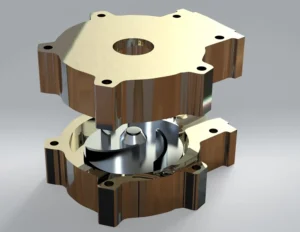
A 3D model of the impeller and volute with a rotating reference frame, a cavitation model for vapor formation and a turbulence model suited to strong rotation. Several suction conditions were compared to track how cavitation develops.
Key Findings
- Cavitation started at the blade leading edges on the suction side, where local acceleration is highest.
- Vapor regions grew well before any noticeable loss of head, so head alone is a late warning sign.
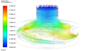
- The same zones coincide with high particle-impact areas, making them the priority for geometry and material changes.
Deliverables
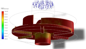
Pressure and vapor-fraction maps, identified cavitation-risk zones and design recommendations for the pump inlet and blade leading edges. This work complements our CFD-based pump design and validation.
Working on a similar problem?
Explore our CFD consulting services or send us your pump, cavitation or slurry-flow question. Learn more about our computational fluid dynamics consulting in Australia.